 In the Arduino ‘microcontrollers’ forum, there have been a few threads on programming an atmega2560 with an usbasp, recently. These made me wonder whether or not usbasp has proper support for AVR’s with >128KB flash. Searching the net to find the answer, is not that obvious. I bought a Chinese usbasp clone so I could do some experimenting myself.
Fuses, BOOTRST, pc wrap around…
The Arduino IDE burns the bootloader to an avr in two avrdude commands. It sets the fuses in the first step and burns the actual bootloader image in a second one. (It also manipulates the lock bits but that is not important in this discussion).
For the atmega 2560 it sets the fuses to lfuse=0xFF, hfuse=0xD8 efuse=0xFD.
Bit 0 of the hfuse is of special importance in this matter:
- hfuse=0xD9, BOOTRST=1: the exception table is at 0x00000, so this is where program execution begins (first entry of that table is the instruction executed when the mcu comes out of reset).
- hfuse=0xD8, BOOTRST=0: the exception vector is at the beginning of the bootload section, in our case at 0x3E000.
If you upload a sketch using a programmer, the whole flash is erased, including the bootloader. The sketch is placed at 0x00000. So th elogical thing to do is set the fuse to 0xD9 to start program execution at the beginning of the flash.
However using hfuse=0xD8 seems to work also. Program execution then starts in the bootload section (which only contains 0xff’s, as we just erased the flash), but will proceed towards the end of memory and will wrap around to 0x00000 and start the sketch. There is one caveat: a sketch bigger than 0x3E000 bytes overlaps the boot loader section, and this trick will not work. However a sketch of that size would be a very rare thing.
It is often believed this wrap around trick does not work for the atmega 2560, but this is not true. If the image is correctly flashed, it does work. It has been reported to work when using an avrispmkII as programmer and in my tests with the ArduinoISP sketch + avrdude 6.1, it worked also. It seems to not work with the usbasp however.
Fischl’s most recent firmware (v1.04) introduced support for flash > 128KB. So it could be expected that the ‘wrap around’ should work. (Otherwise put: upload using programmer with hfuse set to 0xD8 should work). Unfortunately a subtle bug is the reason it does not. Towards the end of this post there is a link to a fix.
Firmware versions < v1.04. have no big flash support so it should not be a surprise wrap around does not work. Likewise it could be expected that burning a bootloader does not work with these versions. Surprise, surprise: it does work correctly! Even with the medieval version v1.02.
What does it mean to support flash > 128KB?
To prepare programming a byte into flash, a programmer sends the “Load Program Memory Page (high or low byte)” command. In this command there is only room for a 2 byte address. This is the address of a two byte word. So this command can address a range of 64K words i.e. 128K bytes.
The atmega2560 has 256 KB flash, so to support this device, the programmer must complete the full address by sending the “Load Extended Address Byte” command upfront.
As an example, take the first two bytes of the bootloader. These should end up at byte addresses 0x3E000 and 0x3E001. To obtain the word address, shift the byte address 1 bit to the right: 0x1F000. So the word address sent in the “Load Program Memory Page High/Low Byte” commands is 0xF000 and the extended address byte is 0x1.
In the sections below, I figure out what firmware is in the usbasp clone I bought. Then, on hand of a few tests, I check whether it supports flash > 128 KB.
Determining the firmware version.
I opted for one of these blue pcb’s, marked “USBASP V2.0 LC Technology”.
In lsusb it shows up as follows:
(On windows the information below can be retrieved from device manager)
$ lsusb
...
Bus 002 Device 019: ID 16c0:05dc Van Ooijen Technische Informatica shared ID  for use with libusb
...
The vendor id is 16c0, product id is 05dc, so the manufacturer string can be read as follows:
$ lsusb -v -d 16c0:05dc | grep Manufacturer
  iManufacturer           1 www.fischl.de
This is an indication it runs the Fischl firmware, or one based on it.
Following command returns the ‘device version’.
$ lsusb -v -d 16c0:05dc | grep bcdDevice
  bcdDevice            1.02
This ‘device version’ corresponds to the version of the Fischl firmware:
| Version Number | Filename | Features added |
|---|---|---|
| 1.04 | usbasp.2011-05-28.tar.gz | Support for AVR’s with flash > 128KB |
| 1.03 | usbasp.2009-02-28.tar.gz | Support for setting the ISP speed (option -B) |
| 1.02 | usbasp.2007-10-23.tar.gz | Firmware of device I used is based on this version |
So the device I received seems based on Fischl 1.02. The flash is not locked, so I started by reading in the firmware and keeping a backup of it, so I can always restore the vendor firmware if needed.
The vendor firmware is not identical to the Fischl 1.02 release, it is 300B bigger. Although Fischl’s firmware is GPL, I could not find the vendor’s firmware sources.
When using the usbasp, avrdude gives a warning:
avrdude: warning: cannot set sck period. please check for usbasp firmware update.
This is consistent with the firmware being 1.02: setting the ISP speed from avrdude was introduced only in 1.03. As a consequence, avrdude warns it cannot set the default ISP speed. This warning is only relevant if you are working with a slow part for which you explicitly need to set a slow ISP speed.
Now, does the original vendor firmware support flash > 128KB?
No. In Fischl’s firmware this feature was only introduced version 1.04 and from a few tests it is clear that the vendor did not add support for this to the Fischl 1.02 code it started from.
Nevertheless, even without proper support for flash > 128KB, you can accomplish quite a few tasks like correctly programming the booloader near the end of the 256KB flash of the atmega2560.
Let us see how far we get with the vendor’s original firmware. Note that the Fischl 1.02 release can accomplish the same as well:
I started by burning the bootloader into an atmega2560 using the Arduino IDE. It was programmed correctly, I verified this by reading back in, the resulting image, using ArduinoISP sketch (with avrdude v6.1) as a programmer. Moreover, the bootloader is fully functional!
So far so good.
However, if you read back in the image using usbasp, you get an incorrect image: the bootloader appears in the file in two locations: once just below 0x20000 and once just below 0x40000. In reality the bootloader is in there only once, but the firmware’s lack of support for high memory addressing reports the memory above 0x20000 twice, once for the lower 128KB and once for the upper 128KB.
Now, if you flash a blink sketch using ‘Upload using programmer’, the sketch will not work! Why not, what has happened?
Reading back in the image with the ArduinoISP sketch gives the answer: the sketch ended up in memory at 0x20000 instead of the expected 0x000000.
If hfuse is 0xD8, program execution starts at 0x3F000, proceeds towards the end of flash, wraps around to 0x00000 where normally the sketch should be. Probably the program excecution will proceed and in the end reach 0x20000 but the code will not run: it cannot run from this address range.
A side effect of BOOTRST on programming flash through isp?
I did not yet find official documentation confirming this, but the following seems consistent:
If hfuse is set to 0xD8 (BOOTRST=0), and the flash is programmed without first executing the “Load Extended Address Byte” command, the image ends up in high memory (last 128KB). If you do the same thing with the hfuse set to 0xD9, the image will end up in the first 128 KB of flash.
Let us see what this means for both high fuse settings:
hfuse=0xD8
With this fuse set, when programming a bootlader, it will be programmed correctly because the image gets written in the second 128KB half of flash, 2K before the end: at 0x3E000, which is correct.
With this fuse set, as sketch uploaded through “Upload using programmer” does not run, because it ends up at the beginning of the second half of 128KB: at 0x20000.
hfuse=0xD9
Conversely, if you set hfuse to 0xD9, and burn the bootloader (with a single avrdude command, not with the IDE: the IDE would start by setting the fuse to 0xD8), it will end up near the end of the first 128KB: at 0x1E000 and the bootloader will not work. (You have to change the fuse to 0xD8 afterwards, but that will not help).
With this fuse setting, uploading a sketch using “Upload using programmer” will work correctly because the sketch ends up in the first 128KB, at 0x00000, which is where it should be.
In the Arduino fora, the latter is suggested as a solution: set hfuse to 0xD9 when using “Upload using programmer”. But that is actually not needed if the programmer correctly sends “Load Extended Address Byte” commands.
As a side note, the Arduino Reference suggests to first load the bootloader to a fresh microcontroler from factory, before using it. This will set fuses to appropriate values. For the amega2560, this would be 0xD8 and that can indeed perfectly work, also for uploading using a programmer.
A subtle bug in Fischl firmware 1.04
So after upgrading the firmware to v1.04, I expected to be able to use “Upload using programmer” together with using hfuse=0xD8. I uploaded a blink sketch to my mega and to my surprise the led did not start blinking! Aaaaargh!
v1.04 has this subtle bug: the extended address byte is only set if it differs from the previous one. The previous one is incorrectly initialized to 0x00. As a consequence when starting to program the sketch at 0x00000, the “Load Extended Address Byte” is not executed and the sketch still ends up in 0x20000!
A fix.
A fix already lives on the internet, a bit buried in this rc forum thread: http://openrcforums.com/forum/viewtopic.php?f=109&t=1363
I keep a compiled version here: usbasp-v1.5.hex along with the sources it was compiled from.
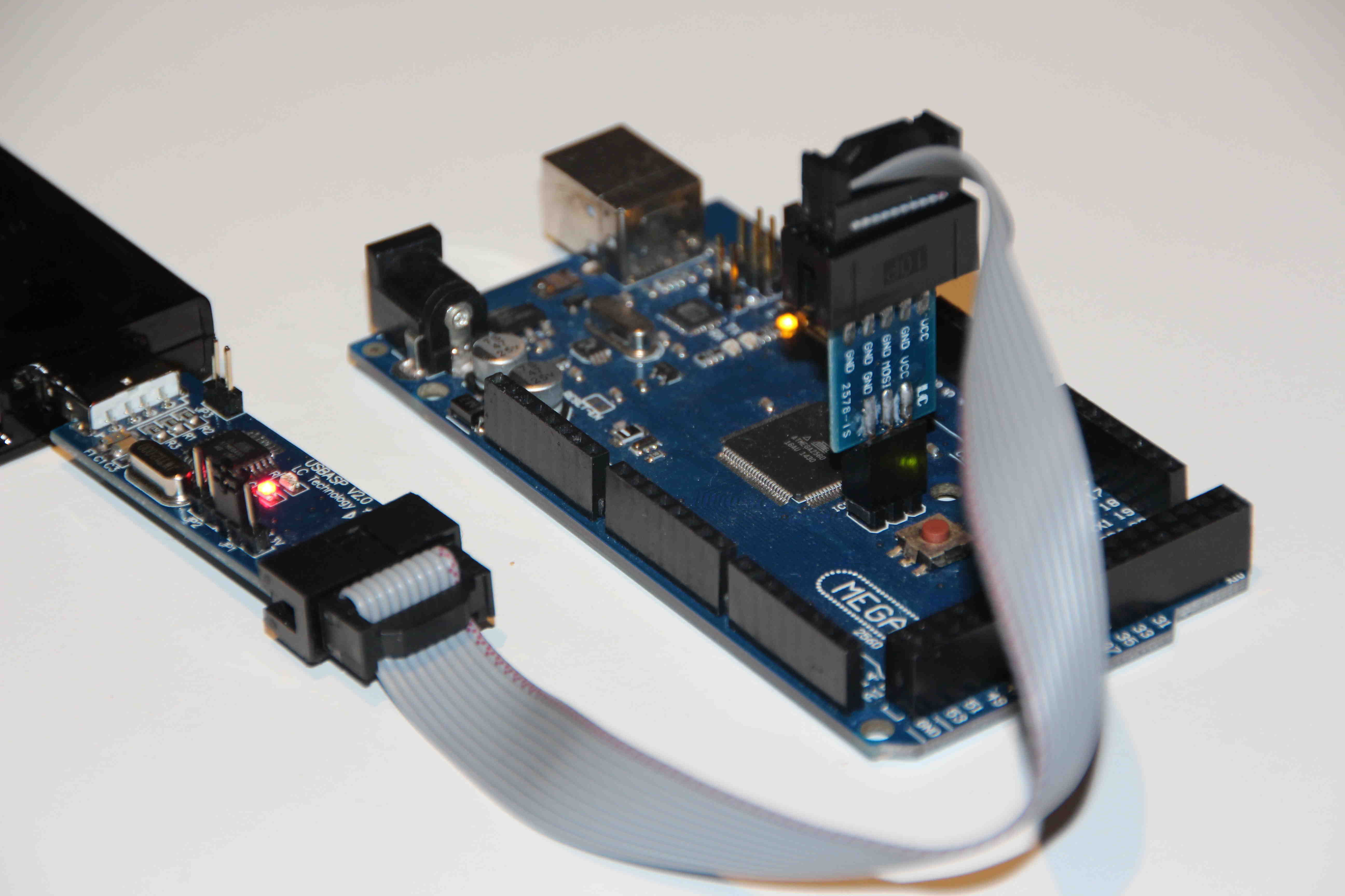
Upgrading the usbasp firmware.
Please decide for yourself whether you want to upgrade the firmware. If you have a different board, check whether its schematics is the same. If the usbasp’s flash is not locked, you can first backup the original firmware, in this case you can restore it any time later.

The picture above shows how this is done with an “ArduinoISP shield”. Note JP2 is closed to allow resetting the atmega8. The 5V jumper is closed too, in order to power the atmega8.
Here are command lines for respectively backing up the original firmware and flashing the new one:
avrdude -v -p m8 -c arduino -P /dev/ttyACM0 -b 19200 -Uflash:r:usbasp-ori.hex:i
avrdude -v -p m8 -c arduino -P /dev/ttyACM0 -b 19200 -Uflash:w:usbasp-v1.5.hex:i
After upgrading the usbasp with this version, it shows up in lsusb with device version 1.05. Connect to an atmega, burn bootloader so hfuse is set to 0xD8 and then burn a blink sketch using “Upload using programmer”. Tadaaah, it blinks.
Moreover you can now:
- flash images spanning more than 128KB.
- set the SPI speed using the -B parameter. (the argument is a float specifying the bit clock period in microseconds. A very useful feature.
Compiling the firmware
The code does not compile with a recent avr-gcc. I settled for using an older avr-gcc, from an arduino 1.0.x IDE that was left on my system:
  $ export PATH=_path_to_arduino-1.0.x_/hardware/tools/avr/bin:$PATH
  $ avr-gcc --version
  avr-gcc (GCC) 4.3.2
  ...
  $ make main.hex
  ...

The tweaks to the code to allow it to build on newer avr gcc tools are quite trivial. It is a mere matter of fixing the PROGMEM references. (that is all I ran into) In reality the original uses of PROGMEM were wrong but the older avr gcc tools were less strict and allowed it. The new tools enforce the proper usage. All you need to do is add a “const” in front of the data type for each declaration that uses PROGMEM. Takes about minute to fix them all. Once corrected, it will build on both the older tools and the newer tools.
then what is the solution to program for uspasb to program the atmega2560.
Thanks a lot, just change “fuses” line and it’ s ok !
What line should be changed into what?
hi, my hardware info
tool: USBasp(chinese)=bFischl firmawre2011, AVRDUDESS
2 targets(inside arduino Mega2560 board) : ( –> i dont want a bootloader !)
target = atmega2560 fuses: L:0xFF, H:0xD9, E:0xFD,LB:empty
target = atmega16u2 fuses: L:0xEF, H:0xD8, E:0xFD,LB:empty
it is work like a charm, best regards.
sorry, i am confused, you work is perfect and i follow it ( the change was for me, not for you).
After experimenting (for the first time, I admit) with a pair of USBasp clones, I eventually found this page.
It’s so nice to see that Thomas Fischl’s work is carried on!
I found that my devices match the LC Tech one you described; even the fw is identical to the one I found in your github space – although mine have three resistors next to the LEDs, and a smaller voltage regulator chip (which means I won’t apply your hardware patches blindly, but there are no 3.3V devices around). No manufacturer ID at all. ProgMode jumper labelled as JP1, voltage selection JP2, JP3 (SCK, obviously) empty.
Did you try to understand the differences between original 1.02 and the lc tech fw? I’ve worked with assembly language before, and think about sitting down over a couple of disassembly listings like I used to do 15 years ago (I managed to fix a bug in a SCSI controller firmware back then). AVR machine code isn’t familiar yet to me, but I’ve also seen Z80 instruction sets some decades ago, and I’m naive enough to have a try. Of course I’d like to avoid duplicating efforts…
Which fuse settings would you recommend for the ATmega8L? What Thomas added to the 1.04 Makefile doesn’t quite match my current values (H D9, L 9F), should I be worried?
Thanks, Steve
I am afraid there is not much potential for a reverse engineering project here: the lc tech fw does not seem to have any special logic inside: it uses a hard coded programming frequency of 94KHZ. (I observed this with a logic analyzer.) The Baite type programmers seem to try a few different clock rates. But they locked their flash so there is no way to read out their code and analyze it. Anyway whatever they do, it can’t be much different from what Bill and I implemented in our 1.6 version, which works quite well and for which the sources are of course available…
For the fuses, you really should verify the differences on hand of the data sheet.
I also do have a ATmega2560 and did use Extreme Burner and USBasp to readout the memory of it…
Why is the bootloader 4x in it…. so every 64Kb you see that bootloader again and again……copy and copy……
So is it possible to make files bigger than 64Kb?? or can you only use 64Kb of that 256Kb???
Hi, Peter: Sorry for bothering, I am a student working on a project. And I’d like to try out your experiments. However I could not find the USBASP version you mentioned. Do you mind if help provide the address on Amazon for USBASP please?
Thanks a lot for your help!
Wenhui
Do you have the source code for your usbasp-v1.5.hex file? I couldn’t find the source code in that forum post that you cited.
Pingback: Come programmare il bootloader della scheda GT2560 V3.0
Hello, I tried to flash the bootloader by mistake and now my mega 2560 is unresponsive to usb flashing the oringal way and also it cannot be detected by traditional iscp way, some people suggested I try using external clock on it and that does make it detect again with USBasp but when I write the bootloader I get error in verification and it dosent restore its original oscilaltor, I m using a mega r3 2560 shield with 16U usb interface