Programming the at89lp family with an Arduino.

at89lp4052

at89lp4052

The at89lp is Atmel’s modern 8051 micro controller family. These mcu’s can fetch one instruction per clock cycle, where the classic 8051 needs 12 cycles. Execution takes 1 to 4 cycles, compared to 12 to 48 for the classic 8051. In the end this makes the new controller 6 to 12 times faster. Alternatively you can run the mcu in ’12 cycle per instruction fetch backwards compatibility’ mode. The choice is made by setting a fuse.

A controller more regularly asked about in the Arduino Microcontrollers forum is the older at89s52 mcu. Actually this is very bare bones micro controller: it has 32 gpio’s, 3 timers, an uart, support for isp and that is about it. It has 256 bytes ram and 8KB flash. Compared to this, the at89lp51ed2 has much more features: spi, i2c, a dac and pwm’s. Besides the 256 bytes internal ram, it has 2KB extended on chip ram and 64KB of flash.

This post is about a modified ArduinoISP version that can program the at89lp family (at least the two members I own: the at89lp4052 and the at89lp51ed2).

At89lp ISP is a bit different from avr ISP in that an extra signal is requiered: slave select (SS). The target is kept in reset as long as th etarget is in in programming mode but during each individual ISP transfer the SS signal has to be pulled down.

This is actually an old project that has been gathering dust in this old branch of my ArduinoISP git hub repo:
https://github.com/PeterVH/ArduinoISP/tree/at89
I recently picked it up again and back ported (or will do so) some ArduinoISP improvements (e.g. getting rid of the delay in hart beat).

Also I changed the wiring a bit, such that it is compatible with the ‘universal ArduinoISP shield’ described in earlier posts. This wiring should work on all Arduino’s. (Well, actually all avr based Arduino’s. I won’t backport the bitbang spi that allows to run on the arm boards).

Below are some pics:

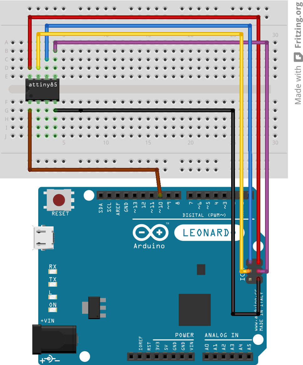
First an Arduino Mega programming an at89lp51ed2 in a breadboard. Remark the ‘Universial ArduinoISP’ wiring: MISO, MOSI and SCK are obtained from the arduino’s ISP header.

mega-lp

Arduino mega programming an at89lp51ed2 in a breadboard.

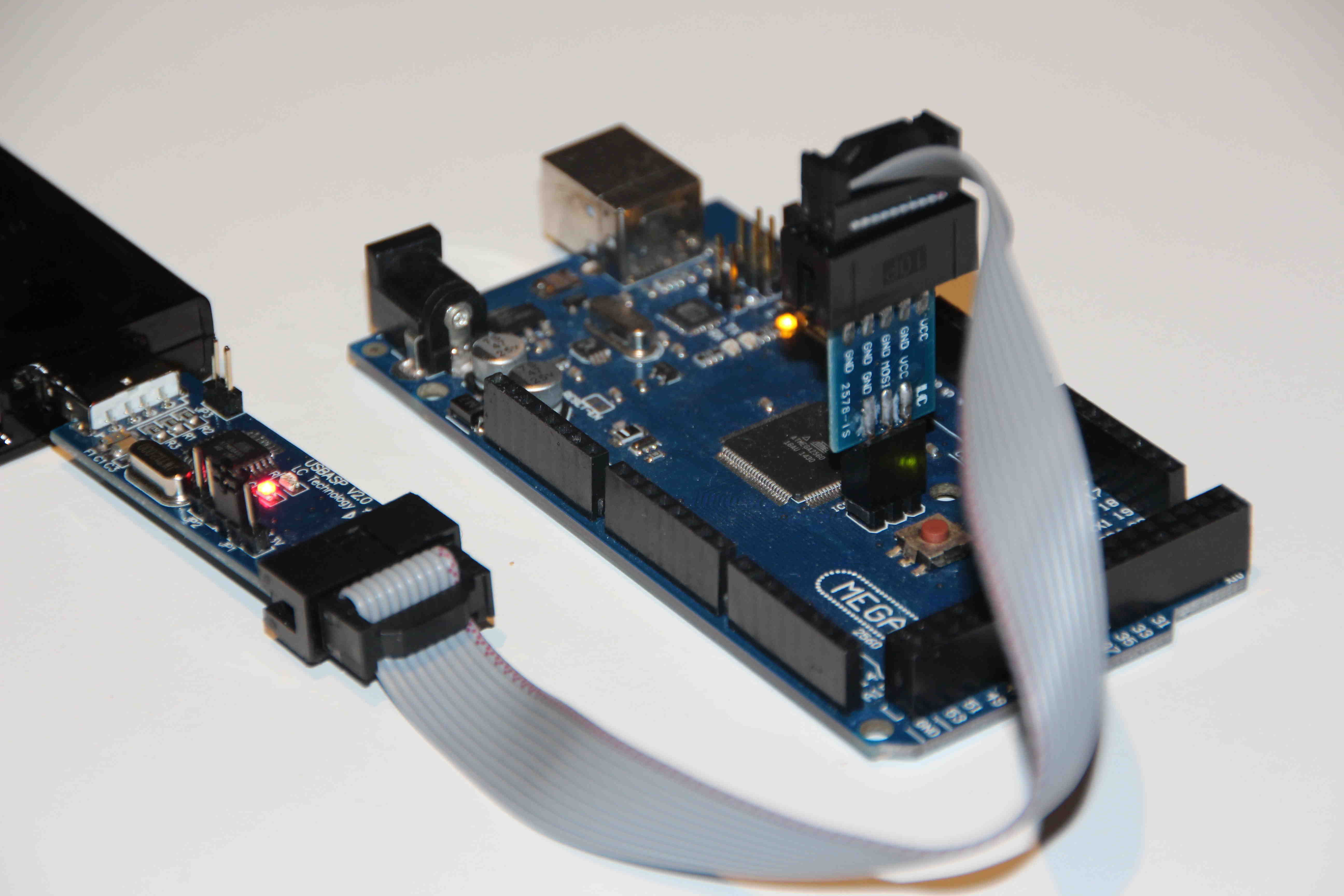
Second, a more tidy setup: a Leonardo fitted with the ‘universal ArduinoISP shield’ programming an at89lp51ed2 sitting in a generic 8051 development board. (Ready to run the knight rider firmware). The extra yellow wire is the extra SS signal. (See also code in the ArduinoISP or at89lp_isp sketches.)

leo-lp

Arduino Leonardo fitted with the ‘universal ArduinoISP shield’ programming an at89lp51ed2 sitting in a generic 8051 development board.

This table lists the connections in a more clear way:

                  Arduino           at89lp
                  =======           ======
 
                     MOSI --------- MOSI' (P1.5) (1)
                     MISO --------- MISO' (P1.6)
                      SCK --------- SCK'  (P1.7)
                       10 --------- RESET
//--R--|<-LED_HB ------ 9 
//--R--|<-LED_ERR ----- 8 
//--R--|<-LED_PMODE --- 7 
                        6 --------- SS (p1.4) 
             IOREF(or 5V) --------- VDD ---||---// 
                                         100nF 
                      GND --------- GND 
                                    POL ------- VDD 
                                    P1.3 --LED->|--R--// (2) 

(1) MOSI', MISO' and SCK' are the 'remapped' SPI signals, they are on different pins than the run time SPI
(2) See examples for a remark on connecting the anode of the led to the mcu

The at89lp_isp sketch

I used this sketch to learn about the at89lp isp protocol. I find it still useful:

  • As a quick test: it can flash a led blink (on pin P1.3) into the target, read out signature…
  • To set the fuses of the at89lp51xx.

When you compile the sketch you can configure building for use with the at89lp4052 or the at89lp51xx chips.
For the latter, you need the #define AT89LP51. (for the at89lp4052 just put the define in comment).

Compile and upload the sketch to the Arduino and connect to the serial line at 115200 baud. Here is a sample session:
(Tested and compiled with ide 1.6.9.)

Send ‘x’: the sketch will report the target device signature, fuses and lock bits.
Send ‘a’: (at89lp51xx only): this programs suitable fuses.
Send ‘x’ again to read the new fuses.
Send ‘r’: the first 100 bytes from flash memory will be read. This will be all FF’s if it is a new chip.
Send ‘e’: erase chip. if you want to program the flash, this step is needed because you can only turn an ‘1’ into a ‘0’, not the other way round, so you must first set every bit to ‘1’.
Send ‘r’ again: now you definitely should see all FF’s
Press ‘w’: the blink program is now programmed
Press ‘r’ to see if the program is really there.
Press ‘p’ to leave programming mode (‘p’ toggles programming mode).
=> the led should now start blinking.

The ArduinoISP sketch

Compiles with ide 1.6.9.
Supports reading, erasing and writing flash. Reads out signature. For now use the at89lp_isp sketch to set the fuses.
You will need an avrdude.conf file that contains specifications for the at89lp. Get it from the repo: data/avrdude-at89lp.conf

An example command line (linux) that flashes the knight-rider.ihx file to the at89lp51xxx:

avrdude -C avrdude-at89lp.conf -P /dev/ttyACM0 -b 19200 -c stk500v1 -p lp51 -U flash:w:knight-rider.ihx

Tested with avrdude 6.3, but any reasonably recent version should do (say from 6.0.1).

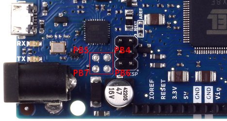
A remark: as always with ArduinoISP you need to make sure auto reset is disabled. For the Leonardo there is noting to do but e.g. the Mega would need a cap between reset and ground to achieve this. In the picture above there is no such cap as I disable auto reset using a modified firmware in the mega’s 16u2 (that is what the blue jumper near the 16u2 is for).

Some 8051 examples…

See examples folder in the repo. They compile with sdcc. Just type ‘make’ to build all samples.

You can configure e.g. the frequency of the crystal you use in hw.h.
This is also the place to configure your target by including the appropriate header: at89lp4052.h or at89lp51x.h
(These headers contain the sfr’s specific for the processor at hand. sfr’s that are standard 8051 are in 8051.h provided by sdcc.)

Here is a quick tour.

Blink. – configurable io

Normally there is not much to say about a blink example. In this case there is. A classic 8051 has “quasi bidirectional io’s” that can be used as input or output without software configuration. The downside is that if you use them as input they are not terribly high impedance and if you use them as output they can’t source a lot of current. To the extent that if you connect a led with its anode side to the io pin and the cathode towards ground (like in the wiring diagram shown above), the io pin can’t source enough current to drive the led. Therefore to blink a led you have to connect the anode to vcc and the cathode towards the io pin, so the microcontroller sinks rather than sources the current.

The at89lp’s ports can be configured as bidirectional, high impedance input, push pull output or, open drain output.

By configuring them as push pull output you can drive a led from the anode side. This is what I did for the blue led in the pictures, using following non generic 8051 code snippet:

    /* at89lp specific: configure P1.3 as push pull output */
    P1M0 &= ~(1<<3);
    P1M1 |= (1<<3);

BTW the memory locations for P1M0 and P1M1 are different for the at89lp4052 and the at89lp51x. These addresses are defined in
at89lpx052.h and at89lp51x.h.

For more information on io port configuration, see data sheet.

Knight rider

Always nice. My favorite.
Does not configure the io port as output so led should point towards mcu.

Melody

8051-tone

Arduino melody sample playing on the at89lp51

This is actually the Arduino melody sample. It uses tone.c which implements the Arduino tone api.
It illustrates how to register interrupt service routines and the use of the timers.
It outputs a signal on P1.3 that is audible if you wire up some amplifier and speaker to that pin.

The usbasp and atmega2560 mystery…

usbasp-mega-zIn the Arduino ‘microcontrollers’ forum, there have been a few threads on programming an atmega2560 with an usbasp, recently. These made me wonder whether or not usbasp has proper support for AVR’s with >128KB flash. Searching the net to find the answer, is not that obvious. I bought a Chinese usbasp clone so I could do some experimenting myself.

Fuses, BOOTRST, pc wrap around…

The Arduino IDE burns the bootloader to an avr in two avrdude commands. It sets the fuses in the first step and burns the actual bootloader image in a second one. (It also manipulates the lock bits but that is not important in this discussion).

For the atmega 2560 it sets the fuses to lfuse=0xFF, hfuse=0xD8 efuse=0xFD.

Bit 0 of the hfuse is of special importance in this matter:

  • hfuse=0xD9, BOOTRST=1: the exception table is at 0x00000, so this is where program execution begins (first entry of that table is the instruction executed when the mcu comes out of reset).
  • hfuse=0xD8, BOOTRST=0: the exception vector is at the beginning of the bootload section, in our case at 0x3E000.

If you upload a sketch using a programmer, the whole flash is erased, including the bootloader. The sketch is placed at 0x00000. So th elogical thing to do is set the fuse to 0xD9 to start program execution at the beginning of the flash.

However using hfuse=0xD8 seems to work also. Program execution then starts in the bootload section (which only contains 0xff’s, as we just erased the flash), but will proceed towards the end of memory and will wrap around to 0x00000 and start the sketch. There is one caveat: a sketch bigger than 0x3E000 bytes overlaps the boot loader section, and this trick will not work.  However a sketch of that size would be a very rare thing.

It is often believed this wrap around trick does not work for the atmega 2560, but this is not true. If the image is correctly flashed, it does work. It has been reported to work when using an avrispmkII as programmer and in my tests with the  ArduinoISP sketch + avrdude 6.1, it worked also. It seems to not work with the usbasp however.

Fischl’s most recent firmware (v1.04) introduced support for flash > 128KB. So it could be expected that the ‘wrap around’ should work. (Otherwise put: upload using programmer with hfuse set to 0xD8 should work).  Unfortunately a subtle bug is the reason it does not. Towards the end of this post there is a link to a fix.

Firmware versions < v1.04. have no big flash support so it should not be a surprise wrap around does not work. Likewise it could be expected that burning a bootloader does not work with these versions. Surprise, surprise: it does work correctly! Even with the medieval version v1.02.

What does it mean to support flash > 128KB?

To prepare programming a byte into flash, a programmer sends the “Load Program Memory Page (high or low byte)” command. In this command there is only room for a 2 byte address. This is the address of a two byte word. So this command can address a range of 64K words i.e. 128K bytes.
The atmega2560 has 256 KB flash, so to support this device, the programmer must complete the full address by sending the “Load Extended Address Byte” command upfront.

As an example, take the first two bytes of the bootloader. These should end up at byte addresses 0x3E000 and 0x3E001. To obtain the word address, shift the byte address 1 bit to the right: 0x1F000. So the word address sent in the  “Load Program Memory Page High/Low Byte” commands is 0xF000 and the extended address byte is 0x1.

In the sections below, I figure out what firmware is in the usbasp clone I bought. Then, on hand of a few tests, I check whether it supports flash > 128 KB.

Determining the firmware version.

I opted for one of these blue pcb’s, marked “USBASP V2.0 LC Technology”.

In lsusb it shows up as follows:
(On windows the information below can be retrieved from device manager)

$ lsusb
...
Bus 002 Device 019: ID 16c0:05dc Van Ooijen Technische Informatica shared ID  for use with libusb
...

The vendor id is 16c0, product id is 05dc, so the manufacturer string can be read as follows:

$ lsusb -v -d 16c0:05dc | grep Manufacturer
  iManufacturer           1 www.fischl.de

This is an indication it runs the Fischl firmware, or one based on it.
Following command returns the ‘device version’.

$ lsusb -v -d 16c0:05dc | grep bcdDevice
  bcdDevice            1.02

This ‘device version’ corresponds to the version of the Fischl firmware:

Fischl firmware versions
Version Number Filename Features added
1.04 usbasp.2011-05-28.tar.gz Support for AVR’s with flash > 128KB
1.03 usbasp.2009-02-28.tar.gz Support for setting the ISP speed (option -B)
1.02 usbasp.2007-10-23.tar.gz Firmware of device I used is based on this version

So the device I received seems based on Fischl 1.02. The flash is not locked, so I started by reading in the firmware and keeping a backup of it, so I can always restore the vendor firmware if needed.

The vendor firmware is not identical to the Fischl 1.02 release, it is 300B bigger. Although Fischl’s firmware is GPL, I could not find the vendor’s firmware sources.

When using the usbasp, avrdude gives a warning:

avrdude: warning: cannot set sck period. please check for usbasp firmware update.

This is consistent with the firmware being 1.02: setting the ISP speed from avrdude was introduced only in 1.03. As a consequence, avrdude warns it cannot set the default ISP speed. This warning is only relevant if you are working with a slow part for which you explicitly need to set a slow ISP speed.


Now, does the original vendor firmware support flash > 128KB?

No. In Fischl’s firmware this feature was only introduced version 1.04 and from a few tests it is clear that the vendor did not add support for this to the Fischl 1.02 code it started from.

Nevertheless, even without proper support for flash > 128KB, you can accomplish quite a few tasks like correctly programming the booloader near the end of the 256KB flash of the atmega2560.

Let us see how far we get with the vendor’s original firmware. Note that the Fischl 1.02 release can accomplish the same as well:

I started by burning the bootloader into an atmega2560 using the Arduino IDE. It was programmed correctly, I verified this by reading back in, the resulting image, using ArduinoISP sketch (with avrdude v6.1) as a programmer. Moreover, the bootloader is fully functional!

So far so good.

However, if you read back in the image using usbasp, you get an incorrect image: the bootloader appears in the file in two locations: once just below 0x20000 and once just below 0x40000. In reality the bootloader is in there only once, but the firmware’s lack of support for high memory addressing reports the memory above 0x20000 twice, once for the lower 128KB and once for the upper 128KB.

Now, if you flash a blink sketch using ‘Upload using programmer’, the sketch will not work! Why not, what has happened?

Reading back in the image with the ArduinoISP sketch gives the answer: the sketch ended up in memory at 0x20000 instead of the expected 0x000000.
If hfuse is 0xD8, program execution starts at 0x3F000, proceeds towards  the end of flash, wraps around to 0x00000 where normally the sketch should be. Probably the program excecution will proceed and in the end reach 0x20000 but the code will not run: it cannot run from this address range.

A side effect of BOOTRST on programming flash through isp?

I did not yet find official documentation confirming this, but the following seems consistent:

If hfuse is set to 0xD8 (BOOTRST=0), and the flash is programmed without first executing the “Load Extended Address Byte” command, the image ends up in high memory (last 128KB). If you do the same thing with the hfuse set to 0xD9, the image will end up in the first 128 KB of flash.

Let us see what this means for both high fuse settings:

hfuse=0xD8

With this fuse set, when programming a bootlader, it will be programmed correctly because the image gets written in the second 128KB half of flash, 2K before the end: at 0x3E000, which is correct.

With this fuse set, as sketch uploaded through “Upload using programmer” does not run, because it ends up at the beginning of the second half of 128KB: at 0x20000.

hfuse=0xD9

Conversely, if you set hfuse to 0xD9, and burn the bootloader (with a single avrdude command, not with the IDE: the IDE would start by setting the fuse to 0xD8), it will end up near the end of the first 128KB: at 0x1E000 and the bootloader will not work. (You have to change the fuse to 0xD8 afterwards, but that will not help).

With this fuse setting, uploading a sketch using “Upload using programmer” will work correctly because the sketch ends up in the first 128KB, at 0x00000, which is where it should be.

In the Arduino fora, the latter is suggested as a solution: set hfuse to 0xD9 when using “Upload using programmer”. But that is actually not needed if the programmer correctly sends  “Load Extended Address Byte” commands.

As a side note, the Arduino Reference suggests to first load the bootloader to a fresh microcontroler from factory, before using it. This will set fuses to appropriate values. For the amega2560, this would be 0xD8 and that can indeed perfectly work, also for uploading using a programmer.

A subtle bug in Fischl firmware 1.04

So after upgrading the firmware to v1.04, I expected to be able to use “Upload using programmer” together with using hfuse=0xD8. I uploaded a blink sketch to my mega and to my surprise the led did not start blinking! Aaaaargh!

v1.04 has this subtle bug: the extended address byte is only set if it differs from the previous one. The previous one is incorrectly initialized to 0x00. As a consequence when starting to program the sketch at 0x00000, the “Load Extended Address Byte” is not executed and the sketch still ends up in 0x20000!

A fix.

A fix already lives on the internet, a bit buried in this rc forum thread: http://openrcforums.com/forum/viewtopic.php?f=109&t=1363

I keep a compiled version here:  usbasp-v1.5.hex   along with the sources it was compiled from.

Upgrading the usbasp firmware.

Please decide for yourself whether you want to upgrade the firmware. If you have a different board, check whether its schematics is the same. If the usbasp’s flash is not locked, you can first backup the original firmware, in this case you can restore it any time later.
ArduinoISP-usbasp-z

The picture above shows how this is done with an “ArduinoISP shield”. Note JP2 is closed to allow resetting the atmega8. The 5V jumper is closed too, in order to power the atmega8.

Here are command lines for respectively backing up the original firmware and flashing the new one:

avrdude -v -p m8 -c arduino -P /dev/ttyACM0 -b 19200 -Uflash:r:usbasp-ori.hex:i
avrdude -v -p m8 -c arduino -P /dev/ttyACM0 -b 19200 -Uflash:w:usbasp-v1.5.hex:i

After upgrading the usbasp with this version, it shows up in lsusb with device version 1.05. Connect to an atmega, burn bootloader so hfuse is set to 0xD8 and then burn a blink sketch using “Upload using programmer”. Tadaaah, it blinks.

Moreover you can now:

  • flash images spanning more than 128KB.
  • set the SPI speed using the -B parameter. (the argument is a float specifying the bit clock period in microseconds. A very useful feature.

Compiling the firmware

The code does not compile with a recent avr-gcc. I settled for using an older avr-gcc, from an arduino 1.0.x IDE that was left on my system:

  $ export PATH=_path_to_arduino-1.0.x_/hardware/tools/avr/bin:$PATH
  $ avr-gcc --version
  avr-gcc (GCC) 4.3.2
  ...
  $ make main.hex
  ...

Burning Zero bootloader with Beaglebone as SWD programmer


OpenOCD has support for bitbanging the jtag or swd protocol over gpio’s. So if you have a board that can run OpenOCD and on which you have access to gpio’s, you can use that as a jtag or swd programmer. The following describes how to use a beaglebone for this purpose but any board with 3V3 gpio’s (e.g. raspberry pie) will do…

bb-m0-z

I followed these instructions to set up the beaglebone. I opted for the debian file system.

Following list of things to install before building OpenOCD will probably save you from having to iteratively install packages untill OpenOCD builds. Of coarse the exact list will change if the initial content of the debian file system changes:

apt-get install autoconf libtool make pkg-config 

Get the OpenOCD sources:

git clone git://git.code.sf.net/p/openocd/code openocd-code

Build openOCD:

cd openocd-code
./bootstrap
./configure --enable-sysfsgpio
make 
make install

openocd is now installed in /usr/local/bin and the scripts it uses are in /usr/local/share/openocd/scripts.

We need an extra config file to describe the beaglebone programmer. I added it here: /usr/local/share/openocd/scripts/interface/bb.cfg. The choice of the gpio’s is up to you, I picked gpio 38 (i.e. gpio1[6], pin header P8_03) and 39 (i.e. gpio1[7], pin header P8_04) as swd_io and swd_sck respectively, so bb.cfg looks like this:

#
# Config for beaglebone interface
#
# This is best used with a fast enough buffer but also
# is suitable for direct connection if the target voltage
# matches bone's 3.3V
#
# Do not forget the GND connection.
#

interface sysfsgpio

# minimal swd setup
sysfsgpio_swdio_num     38
sysfsgpio_swclk_num     39

# (Did not manage to make srst work:)
# sysfsgpio_srst_num      45

Store dot-cc’s bootloader (samd21_sam_ba.bin) in a directory of your choice on the beaglebone.

In that dir, create a openocd.cfg file. OpenOCD will read this file to know what it has to do, and how. In our case the file instructs OpenOCD to use the beaglebone as interface (programmer) and tells it we’re programming a samd21 chip.

source [find interface/bb.cfg]
transport select swd

set CHIPNAME at91samd21g18
source [find target/at91samdXX.cfg]

# did not yet manage to make a working setup using srst
#reset_config srst_only
reset_config  srst_nogate

adapter_nsrst_delay 100
adapter_nsrst_assert_width 100

init
targets
reset halt

If you invoke openocd in this directory, you should see following output.

# openocd
Open On-Chip Debugger 0.10.0-dev-00040-gd52070c (2015-10-11-18:21)
Licensed under GNU GPL v2
For bug reports, read
        http://openocd.org/doc/doxygen/bugs.html
SysfsGPIO num: swdio = 38
SysfsGPIO num: swclk = 39
SysfsGPIO num: srst = 45
adapter speed: 500 kHz
adapter_nsrst_delay: 100
cortex_m reset_config sysresetreq
none separate
adapter_nsrst_delay: 100
adapter_nsrst_assert_width: 100
Info : SysfsGPIO JTAG/SWD bitbang driver
Info : SWD only mode enabled (specify tck, tms, tdi and tdo gpios to add JTAG mode)
Info : This adapter doesn't support configurable speed
Info : SWD IDCODE 0x0bc11477
Info : at91samd21g18.cpu: hardware has 4 breakpoints, 2 watchpoints
    TargetName         Type       Endian TapName            State       
--  ------------------ ---------- ------ ------------------ ------------
 0* at91samd21g18.cpu  cortex_m   little at91samd21g18.cpu  running
target state: halted
target halted due to debug-request, current mode: Thread 
xPSR: 0x21000000 pc: 0x000028f4 msp: 0x20002c00

OpenOCD is now constantly polling the device and it is ready to accept new instructions from us via telnet or gdb. You could log into openocd using telnet from your pc (or from the bone) and inspect memory, run code, start debugging…

If on the other hand you are just interested in burning the bootloader, you could add following line at the end of openocd.cfg and start openocd again.

at91samd bootloader 0; program samd21_sam_ba.bin verify reset; shutdown

OpenOCD should now produce following extra report about the flashing operation.

** Programming Started **
auto erase enabled
Info : SAMD MCU: SAMD21G18A (256KB Flash, 32KB RAM)
wrote 16384 bytes from file samd21_sam_ba.bin in 4.120137s (3.883 KiB/s)
** Programming Finished **
** Verify Started **
verified 6328 bytes in 0.575388s (10.740 KiB/s)
** Verified OK **
** Resetting Target **
shutdown command invoked

The M0 is now ready to receive sketches from the dot-cc IDE.
Remark: if you previously made the modification to the dot-cc lnker script from my previous post, don’t forget to undo this change.

In case you want to restore the dot-org bootloader, use this line as last line in openocd.cfg instead:

at91samd bootloader 0; program Bootloader_D21_M0_150515.hex verify reset; shutdown

Using the Arduino M0 with the arduino.cc IDE and core.

This post is about the plain Arduino M0 from Arduino.org. I bought it at a time the Genuino Zero was not available in Europe. After waiting a few months, I got impatient to try one out and bought the M0… I must say I like this board: it has no on board programmer which makes it a lot more affordable. Moreover for a programmer enthusiast like me it was actually more fun to get this board up and running without the help of the edbg chip.

As a member of the Arduino.cc community, I wanted to use this board with the dot-cc IDE. The most practical way to do so, is to burn the dot-cc bootloader into it. After that, your M0 (or M0 Pro) is almost the same thing as an Arduino Zero.

The M0 Pro has an on board programmer, so burning the bootloader can simply be done via the ‘Burn Bootloader’ menu from the IDE, without the need for additional tools.

The plain M0 has no such on board programmer. You could burn it using an external programmer (see e.g. next post). However, you might not have such a programmer available, or you might just wonder whether sketches built with the dot-cc IDE can be sent to a stock dot-org M0 that still has its original boot loader in place.

That is what this post is about: use the dot-cc IDE to build sketches, pretend you have a Zero by selecting the Zero as board and then send it to the M0. The whole sequence cannot be completed from within the IDE. That is why towards the end of this post, a script is presented that executes the complete sequence of building the sketch, post process it and then send it to the M0. That script is also a good example of the Arduino CLI (Command Line Interface).

A good general approach with this technique is to first develop with the dot-cc ide (just as if you had a Zero). If your application requires extra libraries, just install them in the usual way.

In this process keep in mind there are after all a few hardware differences between the M0 and the Zero:

  • Digital pins 2 and 4 are swapped
  • ATN pin is not connected on the M0
  • Serial port selection is also a bit tricky:
    • Serial will print to the uart (pins 0 and 1) on the M0
    • SerialUSB prints to the native (only) usb port on the M0

The above differences could be streamlined by creating “variant” files, but I choose to not go that far…

Once your sketch compiles, it should work on the M0 too (modulo the hardware differences). You may want to use the m0.sh script to rebuild it and send it to the M0. You can move your sketch folder to a folder of your choice, it does not need to be in the sketchbook folder. Referenced libraries can stay in the sketchbook/libraries folder…

What is needed to compile a sketch, post process the compiled binary and send it off to the M0.

If you compile a sketch with the dot-cc IDE, just like that, it produces an image that does not end up in flash on the location where the dot-org bootloader expects it.

To create a suitable image, the  linker script used by the dot-cc IDE must be modified. The dot-cc IDE’s board manager maintains files for a given core in the .arduino15 sub dir of your home dir (the description below this point is for linux but for windows, you can carry out an equivalent procedure). In there, locate the support package for the Zero in which you’ll find the linker script. Mine was at: .arduino15/packages/arduino-beta/hardware/samd/1.6.1-build-34/variants/arduino_zero/linker_scripts/gcc/flash_with_bootloader.ld

Find the line describing the flash area:

FLASH (rx) : ORIGIN = 0x00000000+0x2000, LENGTH = 0x00040000-0x2000 /* First 8KB used by bootloader */

And change it into:

FLASH (rx) : ORIGIN = 0x00000000+0x4000, LENGTH = 0x00040000-0x4000

Now the dot-cc IDE will create an image suitable for the dot-org bootloader, be it that it is in the elf file format and we need a hex file. We can easily convert the elf image produced by the dot-cc IDE, using objcopy. I’ll explain that later, in the script presented below.

So, at this point we have a .hex file suitable for running on the M0. Let’s see how we can get it there.

The dot-org IDE uploads sketches to the M0’s bootloader using avrdude, whereas the dot-cc IDE uses bossac to upload to the Zero. So we’ll have to use avrdude. We need the avrdude provided by the dot-org IDE, a stock avrdude version does not work.

The dot-org avrdude version is compiled without support for elf images, this why we need to convert to .hex.

We’ll have to press the reset button ourselves before uploading the sketch. But that works very reliably: after pressing reset the bootloader waits about 10 seconds for a sketch to arrive. It indicates this condition by blinking the led rapidly. It is easy to synchronize pressing reset with firing up avrdude. Also, uploading the sketch is very fast.

The m0.sh script.

Because it is not very handy to compile the sketch in the IDE, find out where it has built the elf file, convert it and invoke avrdude manually, I wrote a script that automates this procedure. The sketch is built using the new CLI (Command Line Interface) of the IDE. This is actually practical, you can edit the sketch in any editor and build/upload it with the script.

Say you have a sketch named ArduinoISP.ino, the script expects it to be in a sub folder (of the current working directory) named ArduinoISP. The script places all build files in sub folder: build/ArduinoISP.

In this example, invoke the script as:

./m0.sh ArduinoISP

Here is the script:

#!/bin/bash

# m0.sh: compiles a sketch and sends it off to the arduino M0

if [ $# -lt 1 ]; then
        echo -e "\nUsage: $0 <sketch_dir> [serial_port]\n"
        exit 1
fi

# sketch dir, trim trailing slash:
SKETCH=$(echo $1 | sed 's:/*$::')

# serial port
if [ $# -gt 1 ]; then
        PORT=$2
else
        PORT=/dev/ttyACM0
fi

# the dot-org ide is installed here:
DOT_ORG=/opt/arduino-1.7.6-linux32

# the dot-cc ide is installed here:
DOT_CC=/opt/arduino-nightly

# compile sketch:
${DOT_CC}/arduino \
        --verify \
        --verbose-build \
        --board arduino-beta:samd:arduino_zero_native \
        --pref build.path=build/${SKETCH} ${SKETCH}/${SKETCH}.ino || exit

# create a hex file:
${DOT_ORG}/hardware/tools/gcc-arm-none-eabi-4.8.3-2014q1/bin/arm-none-eabi-objcopy \
        -O ihex -R .eeprom \
        build/${SKETCH}/${SKETCH}.ino.elf build/${SKETCH}/${SKETCH}.ino.hex

echo -e "\n\n\nPress the RESET button now..."
echo -e "Then press ENTER to continue...\n\n\n"
read

# upload sketch:
${DOT_ORG}/hardware/tools/avr/bin/avrdude \
        -C ${DOT_ORG}/hardware/tools/avr/etc/avrdude.conf \
        -v -v -patmega2560 -cstk500v2 -b57600 \
        -P ${PORT} \
        -Uflash:w:build/${SKETCH}/${SKETCH}.ino.hex:i

Remarks:

  • A script like this, that uses the CLI, risks to have a limited validity date. If the conventions change about where to place the various files needed by the IDE, this script will rapidly be broken…
  • note the script instructs the IDE to use ‘arduino-beta‘ as the ‘package’. At the time of writing the Zero core is still actively worked on. E.g. to be able to run ArduinoISP, I needed a beta version that fixes problems in the USB drivers. If you work with the latest stable version use ‘arduino‘ as package instead. (the package is the name of the sub folder of the .arduino15/packages folder).

ArduinoISP reliability and portability improvements.

It is already two years since my latest post in which I played with the idea of proposing some improvements for the ArduinoISP sample sketch. I finally decided to make some time for this so I can scrap it from my bucket list. See Arduino issues 3321 and 3500.

Two kind of changes are targeted: changes to make ArduinoISP run on more Arduino models and changes that improve reliability.

The reliability changes are rather trivial, but nevertheless effective. I have found that ArduinoISP in all its simplicity works quite well but that there are only a few small unfortunate problems that ruined the user experience for a lot of people and gave ArduinoISP its bad reputation. That is a pity because they are easy to fix.

Seen this reputation I found it a good idea to describe a hand full of use cases I collected for testing the improvements. For some of these use cases it even not commonly known that ArduinoISP can handle them. The idea is to run this test suite on a representative set of Arduino models, and on the three operating systems supported by the IDE. Hopefully such a test report will give people confidence that ArduinoISP works reliably and that they will give it a try.

Models tested

Arduino Uno, Due, Zero, Mega, Leonardo and Duemilanove (as a representative for ftdi based boards).

A more universal wiring

The official ArduinoISP tutorial and a zillion of other ones on the web, show how to obtain the MOSI, MISO, and SCK signals from an Arduino UNO’s pins 11, 12 and 13.

On an UNO, this will still work with the new sketch. But I prefer a wiring that obtains these signals from the Arduino’s SPI pin header. The new sketch always uses digital pin 10 to reset the target. The advantage of this wiring is that it works without changes or jumpers, on the UNO, Leonardo, DUE, Mega…

… TODO: diagram here …

I built a simple ‘universal ArduinoISP shield’ according to this wiring. It made testing on the set of Arduino models more practical.

due-mega-z

Due burning bootloader into a Mega.

5V – 3V3

Be careful with 3V3 boards like the DUE or Zero. See also here.

To make no mistakes when testing with all these boards, I took this approach:
– I always power the targets only from the programming Arduino. (No usb cable or other power supply connected to the target…)
– On the ‘universal ArduinoISP shield’ described above, a jumper connects the IORef pin of the programming Arduino is to the power pin of the shield’s outgoing SPI header. (The jumper is always in place in these tests). This way the target is automatically powered with 3V3 when programmed from the Due and with 5V when prgrammed from e.g. The UNO. (Well, the Duemilanove has no IORef pin so there I need an extra wire to the 5V)

Disabling autoreset

ArduinoISP works only if the serial port that is used to connect the PC (avrdude) with ArduinoISP, does not autoreset. This is certainly one of the unfortunate problems mentioned above that costed ArduinoISP its reputation.

The good news is that on the Leonardo, the Due and the Zero, nothing has to be done: on these boards ArduinoISP by default uses the native USB port. This port does not autoreset.

On UNO, Duemilanove, Mega,… autoreset has to be disabled.

IDE

All test cases are carried out using the Arduino IDE 1.6.5, but avrdude 6.1 was used instead of the one shipped with the IDE. See further why.

I used CodingBadly’s attiny core and DrAzzy’s core for the tests with the attiny 841.

avrdude 6.1

ArduinoISP uses the STK500v1 protocol which works with 16bit address values. For the AVR’s flash such an address is the address of a two byte word. So without extra measures, the protocol can only program the first 128MB of flash.

However, avrdude 6.1 comes with some clever fixes that do make it possible to program high addresses with stk500v1. This makes it possible to e.g. reliably burn the bootloader of an atmega2560 using ArduinoISP. (The bootloader is at the end of its 256 KB flash).

On linux, the IDE uses a shell script: <arduino install dir>/hardware/tools/avr/bin/avrdude. You can make the IDE pick the avrdude installed on your system by changing following lines:

export LD_LIBRARY_PATH="`dirname "$0"`/../lib/"
exec -a "$0" "`dirname "$0"`/avrdude_bin" "$@"

into:

exec -a "avrdude" avrdude $@ -v

Most ditributions come with an older version, you’ll have to build avrdude 6.1 from code and install it.

The test suite

I keep the tests here.

1. No target connected.

If no target is connected, ArduinoISP, will read in all ones on its MISO line. So it reads a device signature of 0xffffff. But the protocol between avrdude an ArduinoISP should still be able to correctly convey this bogus signature to avrdude. So the latter should output the dreaded:

avrdude: Device signature = 0xffffff
avrdude: Yikes! Invalid device signature

The programming mode led (green) should light up briefly. The error led (red) should stay dark.
Programming again, should give the same result every time.

2. Burn UNO bootloader

From the “Tools” menu in the IDE: select Arduino/Genuino UNO as Board, select “Arduino as ISP” as programmer, and execute “Burn bootloader”

3. Burn arduino mega bootloader (requires programming above 128KB)

Same as above but select “Arduino/Genuino Mega or Mega 2560” as board.

4. Program an attiny85

Compared to an atmega, an attiny requires a much slower SPI clock to be programmed. So this is a good test case for Arduino’s with a fast hardware SPI clock (the sketch will switch to bitbang spi on those Arduino’s).
The Chaucer4K sketch is used in this testcase, just to test with something bigger than a small led blink sketch.

Tools>Board: ATtiny85 @ 1 MHz (internal oscillator; BOD disabled)
Just use the upload button to upload the sketch. (this works if the target’s fuses already have the correct value)

5. Program an attiny841

This testcase was add because the attiny841 can be programmed with ArduinoISP but it is very slow. Actually it still has to be investigated why.

Tools>Board: ATtiny841 @ 8 MHz (internal oscillator; BOD disabled)
Just use the upload button to upload the sketch.

6. Program an at89s52

The improved ArduinoISP adds support for the at89s52. (Every once in a while a question about this pops up in the Arduino forum.)

For convenience, in the ArduinoISP-Tests repo,  there is a makefile that compiles a blink and a knight-rider example using sdcc.

7. Chaucer115 to 1284p: Program a big (115KB) sketch into an atmega 1284p

Just to test with a larger image.

8. Chaucer115 to mega: Program a big (115KB) sketch into an arduino mega

Same test, different target.

9. LongStoryShort: Program above 128KB.

An alternative for testing high program addresses.


What do Geoffrey Chaucer and all these knights have to do with it?

knights-tale

These tests were borrowed from optiboot’s test suite. To obtain some volume, these sketches dump the first part of knight’s tale on the serial port and blink some leds to indicate activity.

First part of the ‘Knight’s Tale’, the first tale of the ‘Canterbury Tales’ by Geoffrey Chaucer.
original picture

ArduinoISP on the Due

There may not be a lot of practical value in running ArduinoISP on an Aruino Due. If you have a Due, it is very likely you have at least one classic Arduino at hand for which running ArduinoISP is well known and documented. On the other hand, ArduinoISP is a standard Arduino sample so I find that it should work on any Arduino. Well, it was good fun to make it work…

Due programming bootloader into a Leonardo

Due programming bootloader into a Leonardo

I found an opportunity to start with this when I wanted to upgrade the firmware of my Leonardo

Since Arduino 1.0.3, there is an improved boot loader for Leonardo that is a real must have: upon power-on reset, it jumps immediately to your sketch instead of awaiting programmer commands for some seconds.

Just for the sake of it I decided use my Due for this task.

Due programming an attiny85

Due programming an attiny85

Later on, I tried to program an attiny85. This required some extra measures. The Due’s SPI runs too fast for these targets so I had to use software SPI to slow the Due down.

Wiring, 5V, 3V3…

First thing to take care of was to make sure not to fry the Due which is not 5V tolerant. Connecting it to the ISP port of the Leonardo powered with 5V would probably damage the Due: the Leonardo would drive the MISO signal to 5V. I took a very simple approach: I powered the Leonardo with 3.3V. See red jumper wire between the Due’s 3V3 (don’t accidentally use the adjacent 5V pin) pin and the Leo’s 5V pin.

As usual, my photo’s are lousy, but these are the connections:

Due     | Target (Leonardo, attiny85...)
 MISO   |  MISO
 SCK    |  SCK
 MOSI   |  MOSI
 GND    |  GND
 3.3V   |  Vcc (labeled 5V, on the Leonardo)
 Dig 10 |  RESET

It should be warned not to connect the 5V (!) power pin from the Due’s SPI header to the corresponding pin on the Leonardo (using a flat cable would do this). Like most people on the forum I expected this pin to carry 3V3, and first I was tempted to use it to power the Leonardo. Well it has 5V. OK, trap avoided.

Also when this wiring is in place, don’t connect the Leonardo’s USB cable !

In general, don’t power the target at 5V when doing this.

Get a “Due – ready” version of ArduinoISP


The version of ArduinoISP that comes with the ide is a bit outdated. It does not even compile for the Due because the SPI functionality is implemented using AVR specific SPI registers.


I keep a version here that works on the Due without need for further tweaking, nor patches in the core.

I plan to write more about its details in a later post. It has some options you can configure and it has a few new fixes.

Also for other Arduino’s, this version works out of the box, with a reasonable default configuration. Therefore I think it is a candidate for inclusion in the IDE.  We’ll see…

Edit November 2015: Since Arduino 1.6.6, these modifications are integrated in the IDE.

I wish to thank Sylvan Butler, whose SPI bitbang implementation I started from.

Try it out.

Compile and upload the sketch to your Due. Once that is done it is ready to do ISP. Use the native USB port (see photo).

From this point on, when it comes to programming a target, it makes more sense to use arduino 1.0.x. This is OK, the IDE does not care your ArduinoISP programmer is actually a Due.

Windows users have one more thing to take care of: the ide must be instructed to use “arduino” as programmer instead of “stk500v1”. It is explained here (go to point 7), but looking back on it, I find it more easy to just go into the arduino-1.0.x\hardware\arduino\programmers.txt and change the entry:
   arduinoisp.protocol=stk500v1
into:
arduinoisp.protocol=arduino

That is it. I tested burning the bootloader into my Leonardo using arduino 1.0.3 on linux (Ubuntu 12.04.2 LTS) and on Windows 7 SP1 64bit. I also burned a bootloader into a 328p clocked with16MHz.

It was also possible to burn some led blinking firmwares into an attiny85 clocked@1MHz, internal oscillator.

Disabling auto reset on the Arduino Due

jumper

Autoreset disable jumper
(modified 16u2 firmware)

This post is about a simple modification to the firmware of the atmega16u2 on the Arduino Due board, that makes it possible to disable auto reset on the Due’s programming USB port.

Edit: as Topaz replied, there is a much easier way to disable auto reset: put a 1K resistor between reset and 3V3. Nevertheless the firmware mod described here has the convenience that it disables auto reset while auto upload still works. –  And it is good fun too!

I found this feature was best introduced via a small tour of observations about auto reset on various Arduino types.

Auto reset on classic Arduinos.

On classic Arduinos, the nDTR output pin of the USB to serial converter is connected to the AVR’s nRESET pin. If you start avrdude to upload a sketch, the serial line is opened and the operating system normally brings nDTR low. This is because with a classic modem, nDTR (Data Terminal Ready) indicates to the modem that the “terminal” (the PC) is ready to  for communication. So connecting nDTR to nRESET automatically resets the AVR.

There is a serial capacitor between nDTR and nRESET that starts charging up (through nRESET’s 10K pullup resistor) from the moment nDTR goes low, thus providing for a short reset pulse.

Further there is a diode from nRESET to 5V. This is because when nDTR goes back high, there is momentarily 10V on nRESET. Absence of such a diode was reported to cause unintentional high voltage programming on the AVR.

Sometimes the RTS signal is used instead of DTR.

Most Arduino’s have a trace that can be cut to disable auto reset. On my Duemilanove I soldered a jumper across the trace so I can easily close the trace again if I want auto reset.

Another method mentioned often in the fora is to place a 20uF cap between nRESET and ground that prevents nRESET from being pulled low. See here.

Why disabling auto reset?

The side effect of auto reset is that if you you open the serial port just to see the output of your program, the processor is reset as well. In many (if not most) situations, this is not what you want. However, it looks like over time, Arduino users started considering this behavior as normal and even desired. This is because if the processor is reset and thus the sketch is restarted, the messages sent to the serial line in the beginning of the sketch will nicely show up in your terminal program.

A related problem with auto reset is that when software on your PC opens the serial port and sends data to it, the Arduino resets, its bootloader starts running and it will consume the first bytes sent by the PC…

The Leonardo’s USB port.

The Leonardo has a different behaviour. It does not auto reset if you open the serial port. When the IDE wants to upload a sketch, it has to indicate this intent by “touching” the port at the magic baud rate of 1200bps. Only then auto reset will happen. I find this behaviour more useful. But you lose the feature of catching early println’s in your terminal program. No big deal to me, but apparently it was important enough to for the developers come up with the

while (!Serial)
    ;

idiom. The idea is this: since the sketch is not restarted when the port is opened, we let the sketch wait until the port is opened.

If you have a look at how the boolean operator for class Serial is implemented you’ll see that it returns true when DTR or RTS are asserted i.e. when the port is “open”.

The Due’s native USB port.

The Due’s native USB port works much like the Leonardo’s. So if you want to avoid auto reset on the Due, the simplest way is to use this port. Use SerialUSB instead of Serial in your sketch.

The Due’s programming USB port.

The Due’s programming USB port is a real uart on the sam, connected to an uart on the atmegu16u2 which serves as serial to USB converter. To be able to flash a new sketch into the sam,  the 16u2 must perform a special sequence: it must first pulse high the sam’s erase line, then pulse low nRESET. Of coarse this is not done whenever the serial port is opened: this would erase the flash upon every opening of the serial port! So this erase+reset sequence is only done after the ide has indicated its intent to upload a sketch by opening the port at 1200 bps.

But what happens if you open the serial port at another baudrate than 1200 bps? The erase line is not touched, but what about the reset line?  Well, in this case the sam gets reset too! Clearly the designers opted to be consistent with the behaviour of the Uno, not that of the Leonardo.

Seen the similarity with the Uno, I tried disabling auto reset by installing a 20uF capacitor between the nRESET of the Due and ground. That does not work. Reason is that the Due has no 10nF capacitor between the 16u2’s output and the sam’s nRESET. Therefore, nRESET is pulled low much longer: 200msec. This is enough to drain the capacitor and reset happens.

By the way, there is no buffer between the 16u2’s output pin and the sam’s nRESET. This looks odd because it could damage the Due. Here, it does not hurt because the 16u2’s firmware never drives the pin high, it either pulls it low to reset the sam or configures it as input (high impedance) otherwise. In the latter case, the sam internally pulls up nRESET (to 3V3).

I find the use of a big capacitor to disable auto reset not a proper solution anyway. A jumper would be better. But there is no trace you can cut to disable autoreset like on the Uno.

So I decided to solder jumpers to the four free gpio’s of the 16u2 that are broken out. I modified the firmware such that it only carries out auto reset when a jumper bridge is in place between PB5 and PB7.due_16u2_gpio

See my previous post for where to find the code for the 16u2 firmware.

In Arduino-usbserial.c:

#define JUMPER_SENSE 5
#define JUMPER_GND 7
#define JUMPER_DEBUG 4

JUMPER_GND (PB7) is driven low and JUMPER_SENSE (PB5) senses whether it is jumpered (pulled low) to the first one. This is set up in SetupHardware():

...
/* Jumper pins */
PORTB |=  (1<<JUMPER_SENSE); // pull-up
DDRB  &= ~(1<<JUMPER_SENSE); // input
PORTB &= ~(1<<JUMPER_GND);   // low
DDRB  |=  (1<<JUMPER_GND);   // output

When the PC opens the port, this causes EVENT_CDC_Device_ControLineStateChanged() to get called. Lines in bold were add:

void EVENT_CDC_Device_ControLineStateChanged(USB_ClassInfo_CDC_Device_t* const CDCInterfaceInfo)
{
    ...
    if (Selected1200BPS) {
        /* Start Erase / Reset procedure when receiving the magic "1200" baudrate */
        ResetTimer = 120;
    } else if (!PreviousDTRState && CurrentDTRState) {
        /* Reset on rising edge of DTR
           but only if jumper is NOT in place */
        if (PINB & (1 << JUMPER_SENSE))
            ResetTimer = 30;
    }
}

So, if the line state changes (port opened or closed) at 1200 bps, the ResetTimer is set to 120. The main loop of the firmware will start counting down ResetTimer from 120 to zero, executing the erase+reset sequence in this process.

When opened at another baud rate, the ResetTimer will set to 30. As a consequence the main loop will only execute the last part of the sequence, which is the reset part. The firmware modification makes sure the reset part is only armed if the jumper is NOT in place.

The nice thing is that even with auto reset disabled, uploading sketches still works automatically! This is because when uploading, the magic 1200 bps baud rate is used which still arms the erase+reset sequence!

Modifying the atmega16u2 firmware on the Arduino Due

due-leo_g

Flashing new firmware into the Due’s atmega16u2, using a Leonardo as ISP.

Compiling the firmware

The arduino ide comes with the sources for the 16u2’s firmware. It links against  LUFA  (Lightweight USB framework for AVR’s) which you need to download first. Look for version 100807, not the latest one: the 16u2 firmware from the current ide (1.5.2) does not build as is with the latest version of LUFA. Unzip the zip file in any location on your PC.

Locate the 16u2 firmware directory in the arduino install dir: arduino-1.5.2/hardware/arduino/sam/firmwares/atmega16u2/arduino-usbserial. Copy it into LUFA’s Project sub directory, so you end up with a directory LUFA100807/Projects/arduino-usbserial. In that directory, simply type ‘make’.

In a next post I want to present a modified firmware that allows you to disable autoreset on the Due’s programming USB port…

Flashing the new firmware

There is a tutorial on how to flash new firmware in the atmega16u2 on the Due here. However, the wiring used over there uses pins 10, 11, 12 and 13 on the Arduino that serves as programmer. That does not work on the Leonardo. With the info from my first post, it is straightforward to do this task with a Leonardo too. So following diagram does not bring world shocking new information, but I posted it anyway as I found it practical. Pay attention to the orientation of the Due: its isp header is “upside down” as compared to the SPI header.

due-leo-schema_g

This wiring works on classic Arduino’s like the Uno or Duemilanove too. I find this one easier to remember and to wire.

The procedure in the official tutorial can be used as is with the Leonardo. Except that there is no need to disable autoreset. The procedure is stable, there is not a lot that can go wrong. And if it fails you can try again. Nevertheless I recommend to first try to download the current firmware from the device, just to verify you have a working isp (e.g. for linux, from the ide’s tools dir):
  ./avrdude -C avrdude.conf -c arduino -P /dev/ttyACM0 -b 19200 -p m16u2 -vvv -U flash:r:old.hex:i

I also recommend to install the three leds. If the sketch hangs somewhere (which happens rarely though), you see immedeately what happened.

I did not connect the 5V pins. Both boards are powered by usb. You can compile a new firmware and after upload, the Leo drives nRESET high and the Due is immedeately ready for action again.

Using the Leonardo as USB to serial converter.

Arduino Leonardo used as usb to serial converter.

The green board in the picture above carries an atmega 328p with a Duemilanove bootloader. The Leonardo works as an USB to serial converter and is used to upload sketches to the atmega328p, and to communicate serially with the sketches.

For serial communications and power, the green board has the common 6 pin header you also find on e.g. the Arduino Pro or the Sanguino:

Target processor      Pin                           Serial to usb converter
(Atmega 328p)         Header                        (Leonardo)
GND   ---------------|1|--------------------------- GND
                     |2|                           
5V    <--------------|3|--------------------------- 5V
RX    <--- 1K -------|4|--------------------------- TX
TX    ---- 1K -------|5|--------------------------> RX
RESET <----||--------|6|--------------------------- DTR_PIN (here pin 13 4)
  |       100nF    
 10K
  |
 5V

The DTR pin is used by the Arduino IDE to automatically trigger a reset of the target processor, when it uploads a sketch. The header is meant to be used with an usb to serial converter like e.g. Sparkfun’s  “FTDI simple break out board”. This post is about a sketch and a few hacks in the arduino core that allows you to use the Leonardo  for this purpose.

UPDATE (September 2015): Thanks to Matthijs Kooiman’s work (see Expose CDC settings to sketch #3343), it is now possible to have this functionality without having to hack the arduino core.
Since long before the Leonardo was released (!), Paul Stoffregen has a more optimized sketch. He posted an updated version here: https://github.com/arduino/Arduino/pull/3343#issuecomment-115045979. You need Arduino 1.6.6.

I leave the rest of this post around  as people have used it and come back here. But I believe it is now obsolete, even for work on older cores. You have to modify those cores anyway and therefore I think it is better to add the Serial_.dtr() and Serial_.baud() methods to the old core and rewrite the sketch below without the callbacks. The callbacks below run in interrupt mode. It is difficult to guarantee such a callback is synchronized correctly with normal code. E.g. a flaw in the sketch below is that the loop() function may read a corrupted value of variable ‘baud’. In practice this will not cause a problem as in the next pass through loop(), the baud rate will be set correctly. But this illustrates it is simpler to avoid callbacks under interrupt…
____________________________________

Here is the sketch:
(again: it makes more sense to use the sketch from the link above).

/*
  leo_usb2serial
  Allows to use an Arduino Leonardo as an usb to serial converter.
 */
static long baud = 57600;
static long newBaud = baud;

// this pin will output the DTR signal (as set by the pc)
#define DTR_PIN 13

#define LINESTATE_DTR  1

void lineCodingEvent(long baud, byte databits, byte parity, byte charFormat)
{
  newBaud = baud;
}

void lineStateEvent(unsigned char linestate)
{
  if(linestate & LINESTATE_DTR)
    digitalWrite(DTR_PIN, HIGH);
  else
    digitalWrite(DTR_PIN, LOW);
}

void setup() {
  pinMode(DTR_PIN, OUTPUT);
  digitalWrite(DTR_PIN, LOW);
  Serial.begin(baud);
  Serial1.begin(baud);
}

void loop() {

  // Set the new baud rate
  if(newBaud != baud) {
    baud = newBaud;
    Serial1.end();
    Serial1.begin(baud);
  }

  // copy from virtual serial line to uart and vice versa
  if (Serial.available()) {
    char c = (char)Serial.read();
    Serial1.write(c);
  }
  if (Serial1.available()) {
    char c = (char)Serial1.read();
    Serial.write(c);
  }
}

The sketch’s main job is to forward everything that is received over USB (Serial) onto the real uart (Serial1), and vice versa. That is what happens at the end of loop().

Another task the sketch has to accomplish is to update the uart’s baudrate, whenever the pc changes the baud rate of the virtual com port. When this happens, the arduino core calls lineCodingEvent(baud,...). This routine runs under interrupt so we must take care not to spend too much time in it. Therefore the new baud rate is recorded in newBaud and the actual work is done from loop():

 if(newBaud != baud) {
    baud = newBaud;
    Serial1.end();
    Serial1.begin(baud);
  }

The last thing is to make the DTR signal available on one of the digital pins. Whenever the pc sets or clears DTR of the virtual com port, the arduino core calls lineStateEvent(). This routine also runs under interrupt, but the only thing to do is to adjust the level of the DTR_PIN. Pin 13 is used as DTR_PIN, this way one can observe the led to see what the Arduino IDE does with the DTR signal.

Now we get to the hacking part. Neither lineCodingEvent() nor lineStateEvent() are part of the arduino core. I plan to submit a change request for this, it looks a useful feature to me. However, it is not intrusive to add this feature manually to the core. Besides the changes discussed in my previous post are also needed for this to work, otherwise serial buffer overruns will happen.

Locate the CDC.cpp file and add the lines printed in bold:

void WEAK lineCodingEvent(long baud, byte databits, byte parity, byte charFormat)
{
}

void WEAK lineStateEvent(byte linestate)
{
}

bool WEAK CDC_Setup(Setup& setup)
{
        u8 r = setup.bRequest;
        u8 requestType = setup.bmRequestType;

        if (REQUEST_DEVICETOHOST_CLASS_INTERFACE == requestType)
        {
                if (CDC_GET_LINE_CODING == r)
                {
                        USB_SendControl(0,(void*)&_usbLineInfo,7);
                        return true;
                }
        }

        if (REQUEST_HOSTTODEVICE_CLASS_INTERFACE == requestType)
        {
                if (CDC_SET_LINE_CODING == r)
                {
                        USB_RecvControl((void*)&_usbLineInfo,7);
                        lineCodingEvent(_usbLineInfo.dwDTERate,
                                        _usbLineInfo.bDataBits,
                                        _usbLineInfo.bParityType,
                                        _usbLineInfo.bCharFormat);
                        return true;
                }

                if (CDC_SET_CONTROL_LINE_STATE == r)
                {
                        _usbLineInfo.lineState = setup.wValueL;

                        lineStateEvent(_usbLineInfo.lineState);

                        // auto-reset into the bootloader is triggered when the port, already 
                        // open at 1200 bps, is closed.  this is the signal to start the watchdog
                        // with a relatively long period so it can finish housekeeping tasks
                        // like servicing endpoints before the sketch ends
                        if (1200 == _usbLineInfo.dwDTERate) {
                                // We check DTR state to determine if host port is open (bit 0 of lineState).
                                if ((_usbLineInfo.lineState & 0x01) == 0) {
                                        *(uint16_t *)0x0800 = 0x7777;
                                        wdt_enable(WDTO_120MS);
                                } else {
                                        // Most OSs do some intermediate steps when configuring ports and DTR can
                                        // twiggle more than once before stabilizing.
                                        // To avoid spurious resets we set the watchdog to 250ms and eventually
                                        ...

First, weak symbols are add for lineCodingEvent() and lineStateEvent(). This makes sure that if a sketch does not provide one of the functions, the linker will use these dummy ones.

Then, it suffices to call the functions at the right place. CDC_Setup() is called whenever the Leonardo receives a “control message” , related to the CDC (Communication Device Class) protocol. Line coding and line state are set via such control messages. In the above snippet, the event functions are called after the messages are parsed.

I tried out the sketch by downloading the asciiTable sample using the IDE. The target atmega328p gets autoreset and the baudrate updated to 57600, which is what the Duemilanove bootloader uses. When the download completed, I opened the serial monitor and set it to 9600 baud. Upon reset of the atmega328p, I received the expected output from the asciiTable sketch.

ArduinoISP on the Leonardo

A Leonardo programming an attiny2313

A while ago I noticed this thread about burning an Atmega 328 bootloader with an Arduino Leonardo. It turned out that the ArduinoISP sketch that comes with the arduino ide (version 1.0.1) does not work out of the box on the recent Leonardo model. I decided to buy one and help investigating the problems reported in that thread. Following issues were posted:

In mean time fixes for these issues are committed in the development tree so I expect them to become available in an upcoming release of the ide. Untill then, here is a wrap up on how to use the leonardo as an isp programmer with Arduino 1.0.1. Edit: the fix proposed below in step 3 made it into Arduino 1.0.2, so it is no longer needed. The rest is still applicable.

1. Like in the picture above, connect the target’s MISO/MOSI and SCK signals to the ICSP header of the Leonardo. Don’t connect them to digital pins 11, 12 and 13: on the leo there is no SPI on these pins.

Edit: the picture above is just for setting the scene. Ja450n (thank you) sent me a nice Fritzing drawing, featuring an attiny85,  that is more illustrative:
leo_attiny85

2. In ArduinoISP.ino, change this line:
#define RESET SS
into:
#define RESET 10

Edit November 2015: Since Arduino 1.6.6 this change is already in the IDE.

This states we want to use pin 10, to reset the target mcu .(the brown wire in the picture).
On the leo, SS is not available on arduino pin 10. Actually it is not available on any arduino pin, the atmega pin that exposes SS is used to drive the RX led. Fortunately it is perfectly ok to use pin 10 (or any other digital pin) to drive the target’s reset. (The only requirement for the SS pin is that it is configured as an output (which makes the leo an SPI master). This requirement is fulfilled since it drives the rx led.

3. Locate the CDC.cpp and USBCore.cpp files in your arduino installation directory and apply following modifications (you may want to make a copy first):
In CDC.cpp, the accept routine should look like this:

void Serial_::accept(void)
{
    ring_buffer *buffer = &cdc_rx_buffer;

    int i = (unsigned int)(buffer->head+1) % SERIAL_BUFFER_SIZE;

    // if we should be storing the received character into the location
    // just before the tail (meaning that the head would advance to the
    // current location of the tail), we're about to overflow the buffer
    // and so we don't write the character or advance the head.

    // while we have room to store a byte
    while (i != buffer->tail) {
        int c = USB_Recv(CDC_RX);
        if (c == -1)
            break; // no more data, we're done
        buffer->buffer[buffer->head] = c;
        buffer->head = i;

        i = (unsigned int)(buffer->head+1) % SERIAL_BUFFER_SIZE;
    }
}

In USBCore.cpp, search following snippet:

#ifdef CDC_ENABLED
    USB_Flush(CDC_TX); // Send a tx frame if found
    while (USB_Available(CDC_RX)) // Handle received bytes (if any)
        Serial.accept();
#endif

and change it into:

#ifdef CDC_ENABLED
    USB_Flush(CDC_TX); // Send a tx frame if found
    if (USB_Available(CDC_RX)) // Handle received bytes (if any)
        Serial.accept();
#endif

4. Compile and upload ArduinoISP to the leo.

5. In the ide, open the serial monitor and see to it that the baud rate is not equal to 1200bps. Close the serial monitor again. This step removes the magic baud rate from the serial port which would cause unintentional auto resets.

6. On linux (and probably mac, though I don’t have a mac to try it) you can just go to the “Tools > Programmer” menu and select “Arduino as ISP” as programmer, Now the leo is ready to act as an isp. From here, follow the regular procedure to burn a bootloader in the target. Or you can use avrdude from the command line to burn any hex file in the target…

7. On windows an extra step is required. When selecting “Arduino as ISP” as programmer, the IDE will invoke avrdude and instruct it to use the stk500v1 protocol. Currently (arduino 1.0.2 and 1.0.3) this does not work on windows. It will result in following error message:

avrdude.exe: Send: 0 [30]   [20]
avrdude.exe: Recv:
avrdude.exe: stk500_getsync(): not in sync: resp=0x00

Note that avrdude sends out stuff, but does not receive anything. The leo’s rx led will flash but the tx led stays dark.

As a  temporary work around it was suggested (see here) to define a programmer that instructs avrdude to use the “arduino” protocol instead of “stk500v1”. To do so, create a sub directory named “hardware/leofix” in your sketchbook directory. In that directory install a file “programmers.txt” with following content:

arduinoispleo.name=Arduino as ISP (Leonardo)
arduinoispleo.communication=serial
arduinoispleo.protocol=arduino
arduinoispleo.speed=19200

After restarting the IDE, you will have an entry “Arduino as ISP (Leonardo)” in the “Tools > Programmers” menu. This will do the job on windows too.

The reason stk500v1 does not work is that upon opening the virtual com port, windows/avrdude do not request to assert the “virtual” DTR and RTS signals. The leonardo refuses to send out data under these conditions so it never writes data back to avrdude. When using the arduino protocol, before starting programming, avrdude will briefly deassert DTR and RTS and assert them again. This would trigger autoreset if you were uploading a sketch to an arduino bootloader. But in this work around, we use the side effect that this leaves DTR/RTS asserted during programming which makes the leonardo talk..

I filed an issue for this too:

8. Another reason why ArduinoISP may not work, may come from the fact that the Leonardo is a composite device (it combines a virtual comm port and a HID (keyboard/mouse) in one USB device). Obviously, if you are on an old operating system that does not support composite devices, ArduinoISP will not work, nor will any sketch that uses USB. (Confusingly, uploading sketches is possible because the boot loader is not a composite device.)

Windows has support from XP SP3 on and from Vista SP1 on, Mac has support since Lion, see here for more background.

Since ArduinoISP does not need the HID stuff, a work around is to build it as a “serial port only” sketch. This is described here.