
A Leonardo programming an attiny2313
A while ago I noticed this thread about burning an Atmega 328 bootloader with an Arduino Leonardo. It turned out that the ArduinoISP sketch that comes with the arduino ide (version 1.0.1) does not work out of the box on the recent Leonardo model. I decided to buy one and help investigating the problems reported in that thread. Following issues were posted:
- Issue 998: Leonardo serial buffer overrun when sending more than 64B (from pc to leonardo).
- Issue 995: Unintentional autoreset after uploading a sketch to a leonardo
In mean time fixes for these issues are committed in the development tree so I expect them to become available in an upcoming release of the ide. Untill then, here is a wrap up on how to use the leonardo as an isp programmer with Arduino 1.0.1. Edit: the fix proposed below in step 3 made it into Arduino 1.0.2, so it is no longer needed. The rest is still applicable.
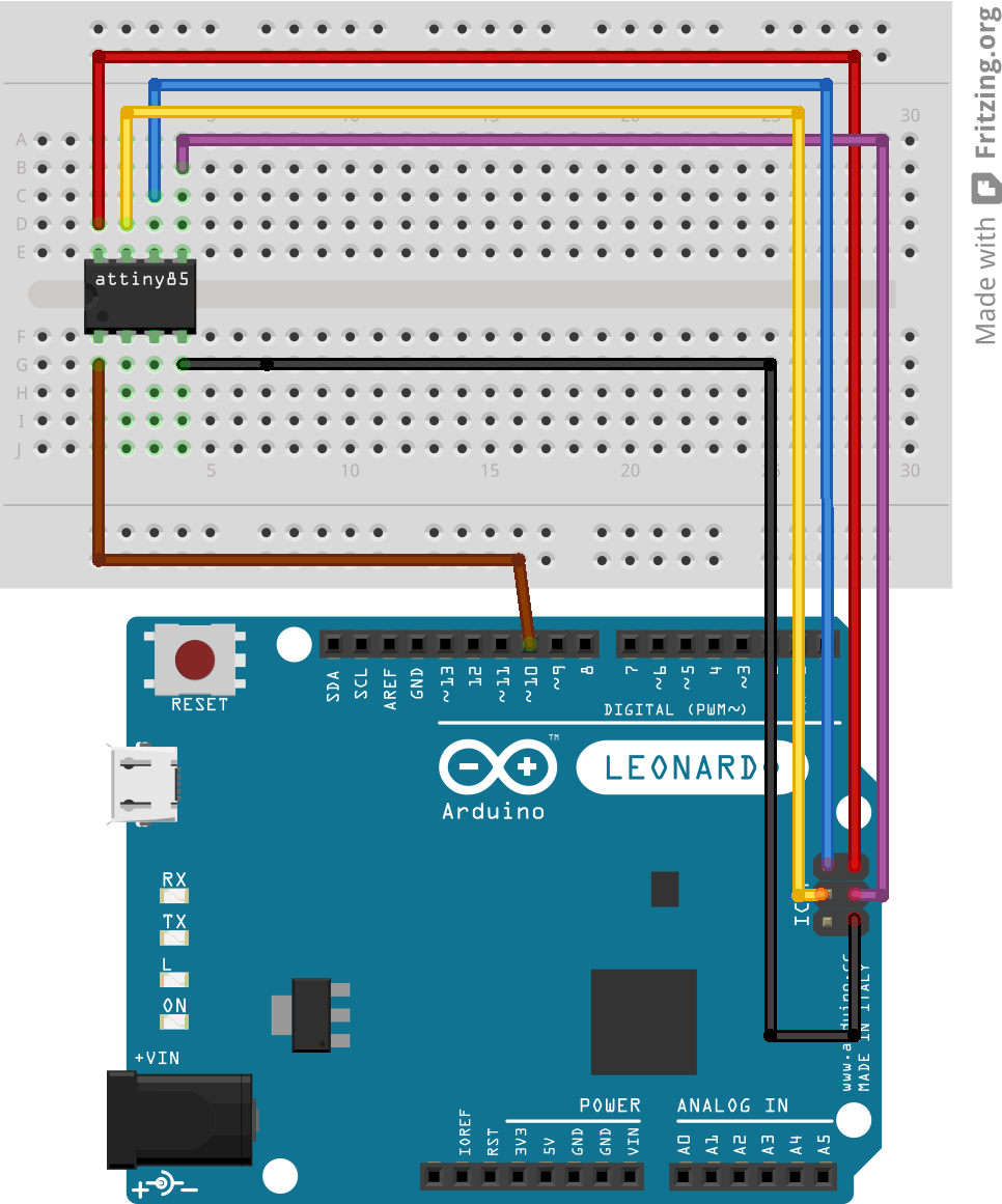
1. Like in the picture above, connect the target’s MISO/MOSI and SCK signals to the ICSP header of the Leonardo. Don’t connect them to digital pins 11, 12 and 13: on the leo there is no SPI on these pins.
Edit: the picture above is just for setting the scene. Ja450n (thank you) sent me a nice Fritzing drawing, featuring an attiny85, that is more illustrative:
2. In ArduinoISP.ino, change this line:
#define RESET SS
into:
#define RESET 10
Edit November 2015: Since Arduino 1.6.6 this change is already in the IDE.
This states we want to use pin 10, to reset the target mcu .(the brown wire in the picture).
On the leo, SS is not available on arduino pin 10. Actually it is not available on any arduino pin, the atmega pin that exposes SS is used to drive the RX led. Fortunately it is perfectly ok to use pin 10 (or any other digital pin) to drive the target’s reset. (The only requirement for the SS pin is that it is configured as an output (which makes the leo an SPI master). This requirement is fulfilled since it drives the rx led.
3. Locate the CDC.cpp and USBCore.cpp files in your arduino installation directory and apply following modifications (you may want to make a copy first):
In CDC.cpp, the accept routine should look like this:
void Serial_::accept(void)
{
    ring_buffer *buffer = &cdc_rx_buffer;

    int i = (unsigned int)(buffer->head+1) % SERIAL_BUFFER_SIZE;

    // if we should be storing the received character into the location
    // just before the tail (meaning that the head would advance to the
    // current location of the tail), we're about to overflow the buffer
    // and so we don't write the character or advance the head.

    // while we have room to store a byte
    while (i != buffer->tail) {
        int c = USB_Recv(CDC_RX);
        if (c == -1)
            break; // no more data, we're done
        buffer->buffer[buffer->head] = c;
        buffer->head = i;

        i = (unsigned int)(buffer->head+1) % SERIAL_BUFFER_SIZE;
    }
}
In USBCore.cpp, search following snippet:
#ifdef CDC_ENABLED
    USB_Flush(CDC_TX); // Send a tx frame if found
    while (USB_Available(CDC_RX)) // Handle received bytes (if any)
        Serial.accept();
#endif
and change it into:
#ifdef CDC_ENABLED
    USB_Flush(CDC_TX); // Send a tx frame if found
    if (USB_Available(CDC_RX)) // Handle received bytes (if any)
        Serial.accept();
#endif
4. Compile and upload ArduinoISP to the leo.
5. In the ide, open the serial monitor and see to it that the baud rate is not equal to 1200bps. Close the serial monitor again. This step removes the magic baud rate from the serial port which would cause unintentional auto resets.
6. On linux (and probably mac, though I don’t have a mac to try it) you can just go to the “Tools > Programmer” menu and select “Arduino as ISP” as programmer, Now the leo is ready to act as an isp. From here, follow the regular procedure to burn a bootloader in the target. Or you can use avrdude from the command line to burn any hex file in the target…
7. On windows an extra step is required. When selecting “Arduino as ISP” as programmer, the IDE will invoke avrdude and instruct it to use the stk500v1 protocol. Currently (arduino 1.0.2 and 1.0.3) this does not work on windows. It will result in following error message:
avrdude.exe: Send: 0 [30]   [20]
avrdude.exe: Send: 0 [30]   [20]
avrdude.exe: Send: 0 [30]   [20]
avrdude.exe: Recv:
avrdude.exe: stk500_getsync(): not in sync: resp=0x00
Note that avrdude sends out stuff, but does not receive anything. The leo’s rx led will flash but the tx led stays dark.
As a temporary work around it was suggested (see here) to define a programmer that instructs avrdude to use the “arduino” protocol instead of “stk500v1”. To do so, create a sub directory named “hardware/leofix” in your sketchbook directory. In that directory install a file “programmers.txt” with following content:
arduinoispleo.name=Arduino as ISP (Leonardo)
arduinoispleo.communication=serial
arduinoispleo.protocol=arduino
arduinoispleo.speed=19200
After restarting the IDE, you will have an entry “Arduino as ISP (Leonardo)” in the “Tools > Programmers” menu. This will do the job on windows too.
The reason stk500v1 does not work is that upon opening the virtual com port, windows/avrdude do not request to assert the “virtual” DTR and RTS signals. The leonardo refuses to send out data under these conditions so it never writes data back to avrdude. When using the arduino protocol, before starting programming, avrdude will briefly deassert DTR and RTS and assert them again. This would trigger autoreset if you were uploading a sketch to an arduino bootloader. But in this work around, we use the side effect that this leaves DTR/RTS asserted during programming which makes the leonardo talk..
I filed an issue for this too:
8. Another reason why ArduinoISP may not work, may come from the fact that the Leonardo is a composite device (it combines a virtual comm port and a HID (keyboard/mouse) in one USB device). Obviously, if you are on an old operating system that does not support composite devices, ArduinoISP will not work, nor will any sketch that uses USB. (Confusingly, uploading sketches is possible because the boot loader is not a composite device.)
Windows has support from XP SP3 on and from Vista SP1 on, Mac has support since Lion, see here for more background.
Since ArduinoISP does not need the HID stuff, a work around is to build it as a “serial port only” sketch. This is described here.

Thank you – I will try it now. Why is arduino pin 10 used for reset, and not just the RESET pin of the ICSP connector?
To be honest, I never thought about that.
But after a quick look in the atmega32u4 data sheet, I think the reset pin cannot be used as an output.
The RESET pin of the ICSP connector is mapped to the RESET pin of the microcontroller on the Arduino board – the ATmega32u4 in the Leonardo’s case. That’s so that the microcontroller on the board can be programmed at the factory.
It worked – I have successfully programmed an ATtiny84. You really saved me.
I realize now that the Leonardo ICSP RESET is for programming the Leonardo onboard processor, and not to control other processors RESET.
Maybe one minor improvement would be to move the three LED and the reset out to be within digital out 0-7. Then it is not needed to connect across the _annoying_ non standard gap 7-8. Some outputs can be used as ground for the LED.
I am trying to use the Leonardo to program the ATtiny45 . Do you have a step-by-step procedure that works? Thank you!!! John Tech
Yes. As written, the instructions given by PeterVH on this page works.
Peter
I have tried those instructions and every other instruction I could find and nothing worked. I tried different software configurations, different hardware libraries and I could never get it to work!! I just gave up and bought an Arduino Uno ver. 3 and everything works just like instructions indicate.
John
This worked, thanks! I was already thinking I blew my chip…
Hey, one dumb question. After doing all that, will I be able to burn Leonardo bootloader to blank ATmega32U4? Thx
Yes.
I successfully flashed a bootloader in my Leonardo using ArduinoISP. I did it from used a Duemilanove though, for the simple reason that I don’t have a second Leonardo. I am confident it will work from the Leonardo too.
The good news is that 1.0.2 contains the proposed fixes. (only step 2 is still needed).
Let me know if it works.
I can confirm that your proposed changes are already built into Arduino1.0.2.
Thanks for your effort!
Thanks. I didn’t notice yet.
I edited the post accordingly.
Hello I have a question
I wanted to use the avr-studio from atmel with the Leonardo as ISP but it don’t work. The avr studio do not recognize the leonardo as ISP
Can anyone tell me why?
Thanks for helping
Hi,
When I choose to use the newly added programmer I get output of
Binary sketch size: 4,810 bytes (of a 28,672 byte maximum)
avrdude: Expected signature for ATmega32U4 is 1E 95 87
Double check chip, or use -F to override this check.
I am defiantly using a Leonardo board and the chip on board is mega32U4. However when I choose to use the original ‘Arduino as ISP’ I get the out of sync error. I have been fiddling with this for the past few days and have been unsuccessful in resolving the issue and any help would be appreciated.
It is not clear to me what are you trying to do.
You want to use a leonardo to load a program via isp into another board that also has an atmega32u4?
Can you select verbose output during downloads in the preferences dialog, and then post the ouput? That way we know at least what signature ArduinoISP returns.
Solved, I was trying to program an AtTiny85 using a Leonardo. After finding this site,
http://hlt.media.mit.edu/?p=1695
and upgrading my ide to 1.0.3 all worked fine. Your leo fix was still required to make this work, but I needed to select the chip that I was trying to program and not the board that I was using to ISP.
Good to hear.
I used the high-low tech link too. It is a good resource for wiring instructions and so on. At that time the core you can download from there did not work for me, but that is apparently fixed now since it worked for you. I used this core instead: http://code.google.com/p/arduino-tiny/
Very neat instructions! Saved me a lot of headache! Thank you very much.
I have one question though. If I do the following in the Arduino IDE 1.0.3, does it mean the ATtiny85 will be running at 8MHz?
1. Tools -> Board -> ATtiny85 (internal 8MHz clock)
2. Tools -> Burn Bootloader
Is this the same as changing the clock prescale register (CLKPR) in the sketch as follow?
void setup() {
cli();
CLKPR = (1<<CLKPCE);
CLKPR = 0;
sei();
}
Hi Chris,
Thanks for letting me know, I always enjoy hearing this stuff worked for someone else!
I am certainly not an attiny expert like the guys from the arduino microcontroller forum or from high-low tech, but combining boards.txt and the data sheet I think the answer is yes, following two options are the same:
Selecting “Tools -> Board -> ATtiny85 (internal 8MHz clock)” sets the low fuse to 0xE2:
CKSEL = 2 (=> 8MHz internal clock)
CKDIV8 = 1 (unprogrammed) => default value of CLKPR = 0000b => clock divided by 1 => 8 MHz
That is the same as selecting “ATtiny85 @ 1 MHz (internal oscillator)” => low fuse is 0x62:
CKSEL = 2 (=> 8MHz internal clock)
CKDIV8 = 0 (programmed) => default value of CLKPR = 0011b => clock divided by 8 => 1 MHz
The code fragment you mention sets CLKPR to 0 so you also run at 8MHz.
I am assuming that you can now program an ATtiny from the Leonardo using version 1.0.3? I have missed a couple of posts.
John
Yes, but note that on windows the work around from step 7 is still needed. I think that was what spoiled it for you last time, wasn’t it?
Hi John,
Yes, by following every steps on this page, I am able to program my ATtiny85 by the Leonardo using Arduino IDE 1.0.3 to do the Blink sketch (flashing LED). My Leonardo is connect to a Windows PC and step 7 is needed.
Hi petervho,
Thank you for the answer. 🙂
In the first method (“Tools -> Board -> ATtiny85 (internal 8MHz clock)”), does the statement delay(1000) in the sketch still mean delay 1sec in real-time? It seems with the second method (sets CLKPR to 0 in the sketch), delay(1000) means delay 1/8 sec in real-time.
Is it possible to set the fuse to make the ATtiny85 to run at internal 16MHz clock? If so, could you please show me the steps?
I am sorry Chris, I don’t have much experience with the attiny and at this moment have no time to dive into this. You may want to dive into the tiny core yourself (sketchbook/hardware/tiny/cores/tiny/wiring.c) to find out whether delay() and micros() take into account the current value of CLKPR. Or try the arduino microcontolers forum, the creators of the tiny core surely hang around over there…
Hi Petervho, you’ve helped me a lot already. I will do some digging myself. Thank you.
First of all great work! But for me I still get a verification error -which I read is the same as the sync error. So I placed the programmers file in the right place, but still avrdude works with stk500v1 but I selected the leonardo programmer (btw. I am using arduino 1.0.3 with Linux and trying oto program an atmega328p).
What am I doing wrong ?
That is weird, but on linux it should not matter, stk500v1 should work as well.
Try turning on verbose output on for uploads in the prferences box in the ide, probably that will give you an indication of what goes wrong. Post the output here if needed.
🙂 Nearly fixed it – the problem was I that the programmer was given twice – once in the leofix file and in the breadboard file….
But what is more important, when I took the generated command line from arduino ide and stripped off the “-D” option (Disable auto erase for flash) it works
Hi,
Thank you for your nice post, but my programmer still won’t work. I used the ATTiny85 @ 8 MHz (internal oscillator; BOD disabled) ‘board’ and applied the Leonardo fix you gave. Without that fix, it gave me a Out of Sync error like you described, but with it enabled it fails also.
The whole log with verbose mode on is quite long, so I’m trying to post only the ‘significant’ parts.
avrdude: please define PAGEL and BS2 signals in the configuration file for part ATtiny85
avrdude: Send: P [50] [20]
avrdude: Recv: . [14]
avrdude: Recv: . [10]
avrdude: AVR device initialized and ready to accept instructions
Reading | avrdude: Send: u [75] [20]
avrdude: Recv: . [14] . [ff] . [ff] . [ff] . [10]
################################################## | 100% 0.02s
avrdude: Device signature = 0xffffff
avrdude: Yikes! Invalid device signature.
Double check connections and try again, or use -F to override
this check.
Thank you!
PS: Sorry for my bad English, I’m Dutch. Are you Dutch also? (Thinking it because of your name)..
Hi Marco,
So the serial communication between pc and leo seems to work ok, but the spi part between leo and target does not:
u [75] [20] <———- this is the read signature command
[14] . [ff] . [ff] . [ff] . [10] <———- all ones read from SPI (miso).
Over here, if I don’t connect miso, I read all zeroes (Device signature = 0x000000. Yikes…).
Is something pulling up miso?
Is the attiny new? (does it still have the factory fuse settings?)
Nee, ik ben Belg.
Normally if you get something like this I would check the connections between the programmer and the chip.
Hi, I recently decided to get into Arduino and went with a Leonardo due to the USB functionality. This article will definitely be helpful in miniaturizing my future projects. Thanks!
I tried making sense of your photo and other pre-leo tutorials for ISP programming and believe i have the wiring setup correct. Would you mind confirming that i’ve got it setup right? http://i.imgur.com/kCnTQnM.png (GND is different, but other than that the ATtiny2313 and ATtiny85 should be the same). Also, feel free to use this image if you think it’d be helpful for others doing the same.
Looks correct.
Thanks. I will paste the image in somewhere…
Pingback: The powerful Attiny Arduino | Corredera Jorge
Pingback: phaq » Blog Archive » Use Arduino Micro as ISP with ATmega on a breadboard
Hi Peter,
could you please help me out on this?
I’m using Arduino Leonado to burn boot loader for ATmega 328P with crystal. But i got this problem
C:\Program Files\Arduino\hardware/tools/avr/bin/avrdude -CC:\Program Files\Arduino\hardware/tools/avr/etc/avrdude.conf -v -v -v -v -patmega328p -carduino -P\\.\COM11 -b19200 -e -Ulock:w:0x3F:m -Uefuse:w:0x05:m -Uhfuse:w:0xDA:m -Ulfuse:w:0xFF:m
avrdude: Version 5.11, compiled on Sep 2 2011 at 19:38:36
Copyright (c) 2000-2005 Brian Dean, http://www.bdmicro.com/
Copyright (c) 2007-2009 Joerg Wunsch
System wide configuration file is “C:\Program Files\Arduino\hardware/tools/avr/etc/avrdude.conf”
Using Port : \\.\COM11
Using Programmer : arduino
Overriding Baud Rate : 19200
avrdude: Send: 0 [30] [20]
avrdude: Send: 0 [30] [20]
avrdude: Send: 0 [30] [20]
avrdude: Recv: . [14]
avrdude: Recv: . [10]
AVR Part : ATMEGA328P
Chip Erase delay : 9000 us
PAGEL : PD7
BS2 : PC2
RESET disposition : dedicated
RETRY pulse : SCK
serial program mode : yes
parallel program mode : yes
Timeout : 200
StabDelay : 100
CmdexeDelay : 25
SyncLoops : 32
ByteDelay : 0
PollIndex : 3
PollValue : 0x53
Memory Detail :
Block Poll Page Polled
Memory Type Mode Delay Size Indx Paged Size Size #Pages MinW MaxW ReadBack
———– —- —– —– —- —— —— —- —— —– —– ———
eeprom 65 20 4 0 no 1024 4 0 3600 3600 0xff 0xff
Block Poll Page Polled
Memory Type Mode Delay Size Indx Paged Size Size #Pages MinW MaxW ReadBack
———– —- —– —– —- —— —— —- —— —– —– ———
flash 65 6 128 0 yes 32768 128 256 4500 4500 0xff 0xff
Block Poll Page Polled
Memory Type Mode Delay Size Indx Paged Size Size #Pages MinW MaxW ReadBack
———– —- —– —– —- —— —— —- —— —– —– ———
lfuse 0 0 0 0 no 1 0 0 4500 4500 0x00 0x00
Block Poll Page Polled
Memory Type Mode Delay Size Indx Paged Size Size #Pages MinW MaxW ReadBack
———– —- —– —– —- —— —— —- —— —– —– ———
hfuse 0 0 0 0 no 1 0 0 4500 4500 0x00 0x00
Block Poll Page Polled
Memory Type Mode Delay Size Indx Paged Size Size #Pages MinW MaxW ReadBack
———– —- —– —– —- —— —— —- —— —– —– ———
efuse 0 0 0 0 no 1 0 0 4500 4500 0x00 0x00
Block Poll Page Polled
Memory Type Mode Delay Size Indx Paged Size Size #Pages MinW MaxW ReadBack
———– —- —– —– —- —— —— —- —— —– —– ———
lock 0 0 0 0 no 1 0 0 4500 4500 0x00 0x00
Block Poll Page Polled
Memory Type Mode Delay Size Indx Paged Size Size #Pages MinW MaxW ReadBack
———– —- —– —– —- —— —— —- —— —– —– ———
calibration 0 0 0 0 no 1 0 0 0 0 0x00 0x00
Block Poll Page Polled
Memory Type Mode Delay Size Indx Paged Size Size #Pages MinW MaxW ReadBack
———– —- —– —– —- —— —— —- —— —– —– ———
signature 0 0 0 0 no 3 0 0 0 0 0x00 0x00
Programmer Type : Arduino
Description : Arduino
avrdude: Send: A [41] . [80] [20]
avrdude: Recv: . [14]
avrdude: Recv: . [02]
avrdude: Recv: . [10]
avrdude: Send: A [41] . [81] [20]
avrdude: Recv: . [14]
avrdude: Recv: . [01]
avrdude: Recv: . [10]
avrdude: Send: A [41] . [82] [20]
avrdude: Recv: . [14]
avrdude: Recv: . [12]
avrdude: Recv: . [10]
avrdude: Send: A [41] . [98] [20]
avrdude: Recv: . [14]
avrdude: Recv: . [00]
avrdude: Recv: . [10]
Hardware Version: 2
Firmware Version: 1.18
Topcard : Unknown
avrdude: Send: A [41] . [84] [20]
avrdude: Recv: . [14]
avrdude: Recv: . [00]
avrdude: Recv: . [10]
avrdude: Send: A [41] . [85] [20]
avrdude: Recv: . [14]
avrdude: Recv: . [00]
avrdude: Recv: . [10]
avrdude: Send: A [41] . [86] [20]
avrdude: Recv: . [14]
avrdude: Recv: . [00]
avrdude: Recv: . [10]
avrdude: Send: A [41] . [87] [20]
avrdude: Recv: . [14]
avrdude: Recv: . [00]
avrdude: Recv: . [10]
avrdude: Send: A [41] . [89] [20]
avrdude: Recv: . [14]
avrdude: Recv: . [00]
avrdude: Recv: . [10]
Vtarget : 0.0 V
Varef : 0.0 V
Oscillator : Off
SCK period : 0.1 us
avrdude: Send: A [41] . [81] [20]
avrdude: Recv: . [14]
avrdude: Recv: . [01]
avrdude: Recv: . [10]
avrdude: Send: A [41] . [82] [20]
avrdude: Recv: . [14]
avrdude: Recv: . [12]
avrdude: Recv: . [10]
avrdude: Send: B [42] . [86] . [00] . [00] . [01] . [01] . [01] . [01] . [03] . [ff] . [ff] . [ff] . [ff] . [00] . [80] . [04] . [00] . [00] . [00] . [80] . [00] [20]
avrdude: Recv: . [14]
avrdude: Recv: . [10]
avrdude: Send: E [45] . [05] . [04] . [d7] . [c2] . [00] [20]
avrdude: Recv: . [14]
avrdude: Recv: . [10]
avrdude: Send: P [50] [20]
avrdude: Recv: . [14]
avrdude: Recv: . [10]
avrdude: AVR device initialized and ready to accept instructions
Reading | avrdude: Send: u [75] [20]
avrdude: Recv: . [14] . [00] . [00] . [00] . [10]
################################################## | 100% 0.02s
avrdude: Device signature = 0x000000
avrdude: Yikes! Invalid device signature.
Double check connections and try again, or use -F to override
this check.
avrdude: Send: Q [51] [20]
avrdude: Recv: . [14]
avrdude: Recv: . [10]
avrdude done. Thank you.
Hi Tony,
This is similar to one of the comments above: serial (USB) communication between pc and leo is ok, but the leo only receives zero’s from the target over spi. The target might have its fuses set such that isp does not work (or only works with a crystal), but most of the time avrdude’s advise is what helps you out: “Double check connections…”. Place caps and crystal close to the avr (without wires)… Feel free to post a picture of the setup if it refuses to collaborate…
petervho,
thank you very much ,this worked for me with Leonardo board – linux 64 bit- Arduino nightly.
I lost a lot of time before to know that ,as you wrote,there is not SPI on 11 to 13 pins,like others guide walks through.
Hi petervho,
this worked for me too with my Leonardo, Win7 64 bit, Arduino 1.0.5.
Many Thanks!
Hi Peter,
Thanks
Worked for an Atmel Studio 6 compiled Hex file, programming an Orangutan Baby B328, via MSDOS command line AVRDude.
Note the non-use of the Arduino IDE.
Thank you Peter, it works perfectly 🙂
I am using Arduino 1.5.6-r2 under OSX Mavericks. I can successfully program an ATTiny85 now.
I have a question: Can I use this same setup to program an ATTiny2313? As I see it, wiring wise the GND (black wire) must go to pin 10 of the ‘2313. The other wires stay the same. Is this correct?
Thank you
Yes.
Thank you. When I click on “Burn Bootloader”, I get:
avrdude: Yikes! Invalid device signature.
Double check connections and try again, or use -F to override this check.
I have the 5 wire connections exactly as for the ’85, the only difference being that the GND wire is moved from pin 4 to pin 10 on the ‘2313. If I then reconnect the 5 wires to an ’85 everything works fine again. I use the core from http://code.google.com/p/arduino-tiny/
Any ideas? 🙂
What is the signature read from the target? (select verbose output during upload in the preferences tab).
Hello Peter,
it only work with ATMega328 right? not work with ATMega328P.
i tried many times but it still can’t burn boot loader for it
I used Leonardo as ISP
Regards
It works with both. Certainly with 328p, the uno has an 328p. Is the signature sent back still 00 00 00, like in your previous post? (then I cant’t help more than what I previously replied).
Peter, your article ended a week of frustration and headscratching – thanks so much!
Working for me on Arduino Micro, attiny85 and IDE 1.0.6
I tried with IDE 1.0.6 and 1.6 rc1 but I cant get it working. May anyone help me?
I opened the official ISP sketch, changed the reset to pin 10 and uploaded this to my leonardo. I connected all wires with a 6 pinheader cable (I did this several times, I also programmed an own ISP sketch so i should know what I am doing) and then selected Arduino as ISP and Uno as board and tried to burn the bootloader. All I get is avrdude: stk500_getsync(): not in sync: resp=0x00
Any idea what I did wrong?
Whoops. the programmers entry with protocol arduino fixed it.
Hi
I get this message when trying to burn bootlader using Arduino micro
avrdude: Expected signature for ATmega32U4 is 1E 95 87
Double check chip, or use -F to override this check.
Is it an atmega32u4 you want to burn? The board type in the IDE should be the type of the target not the type of the programmer.
Perfect article helped me greatly. Spend a large portion of the night trying to program my ATTiny85 and your article gone me the results I need. Keep up the good work.
Trying to use Leo to burn onto 32u4. Adruino 1.6.3 no long has an ArduinoISP.ino file. Says to get file from a dead link:
“You can download the ArduinoISP firmware source files from:
https://github.com/arduino/ArduinoISP“
Use this:
https://github.com/NicoHood/HID/wiki/Arduino-as-ISP
Thanks, gave up trying to use the Leo and dig up an UNO. Less hassle, worked in minutes (rather that the days I spent trying to figure out the issues with Leo.)
Cheers!
That is a pity. Once you have it set up, a leonardo is much more reliable than an uno, for ArduinoISP:
– no need to disable autoreset.
– more stable serial communication (USB). E.g. the delay() in heartbeat(), causes lost characters from the uart on an uno, when selecting a higher baud rate., or simply if timings change between Arduino releases…
Strange, my installation does have one.
Well, I only need to program a couple of boards and I didn’t need any unique settings.
As for the ArduinoISP, I found it under examples. I was looking in Arduino > hardware > arduino > avr > firmwares > arduinoISP.
I’m not trying to disparage others from using the Leo, I just didn’t have the time to make it work.
No problem.
B.t.w. the folder you were looking in is a place holder for the firmware for the ArduinoISP board, not the sketch. It is confusing they gave the board a name that was already used for a sketch that everybody knows. The sketch is here: arduinoinstalldir/examples/ArduinoISP/ArduinoISP.ino
Doubly confusing that it’s an “example”. IMHO 🙂
Pingback: Arduino a ATTINY85 | Coses que passen
I used this tutorial to “Burn Bootloader” with a Leonardo onto another Leonardo that was somehow stuck and could not be programmed anymore.
In spiete of the great tutorial, I still experienced problems burning the bootloader and it took me serveral days and the relentless helf of dmjlambert at http://forum.arduino.cc to figure out, that the new programmer created in step 7 was always using COM1 port, no matter what I selected under Tools > Port.
I came up with a more complete version of the “Arduino as ISP (Leonardo)” programmer, which works perfectly for me (Win 7 x64).
arduinoispleo.name=Arduino as ISP (Leonardo)
arduinoispleo.communication=serial
arduinoispleo.protocol=arduino
arduinoispleo.speed=19200
arduinoispleo.program.protocol=arduino
arduinoispleo.program.speed=19200
arduinoispleo.program.tool=avrdude
arduinoispleo.program.extra_params=-P{serial.port} -b{program.speed}
Also for me it did not work to put this code to a newly created programmers.txt in “hardware/leofix” in my sketchbook directory. Instead I had to add it to “C:\Program Files (x86)\Arduino\hardware\arduino\avr\programmers.txt”
@petervho:
You may want to add this to your tutorial, after you confirmed my findings.
Thanks soo much Mark! It took me hours, but with your additional lines it finally worked!!!! ( I’am using arduino 1.6.7 and the Leonardo )
Before that I had the error that ‘program.tool’ was missing!
Great!
skunkjoe
Pingback: Arduino (UNO) als ISP-Programmer | wer bastelt mit?
Pingback: Arduino Micro as ISP (flashing the bootloader of an Arduino Leonardo) – and thus goes by another day
Pingback: attiny85 DIY Programmer – and thus goes by another day